


TP-6069 6/0312 Section 4 Exhaust System
4.3 Exhaust System Location,
Mounting, and Installation
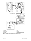
Mount the silencer independently to eliminate stress on
the exhaust system and the exhaust manifold/mixer
elbow. SeeSection 7 for the mixer elbow water linehose
size. See Figure 4-1 for the exhaust connection to the
mixer elbow. Provide an adequate hose length from the
exhaust mixer to the silencer to allow for generator set
movement.
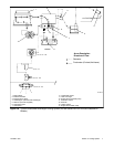
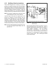
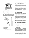
1
TP-5586-6
1. Water/exhaust outlet
Figure 4-1 Mixer Elbow/Exhaust Connection,
Typical
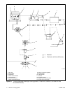
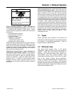
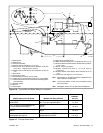
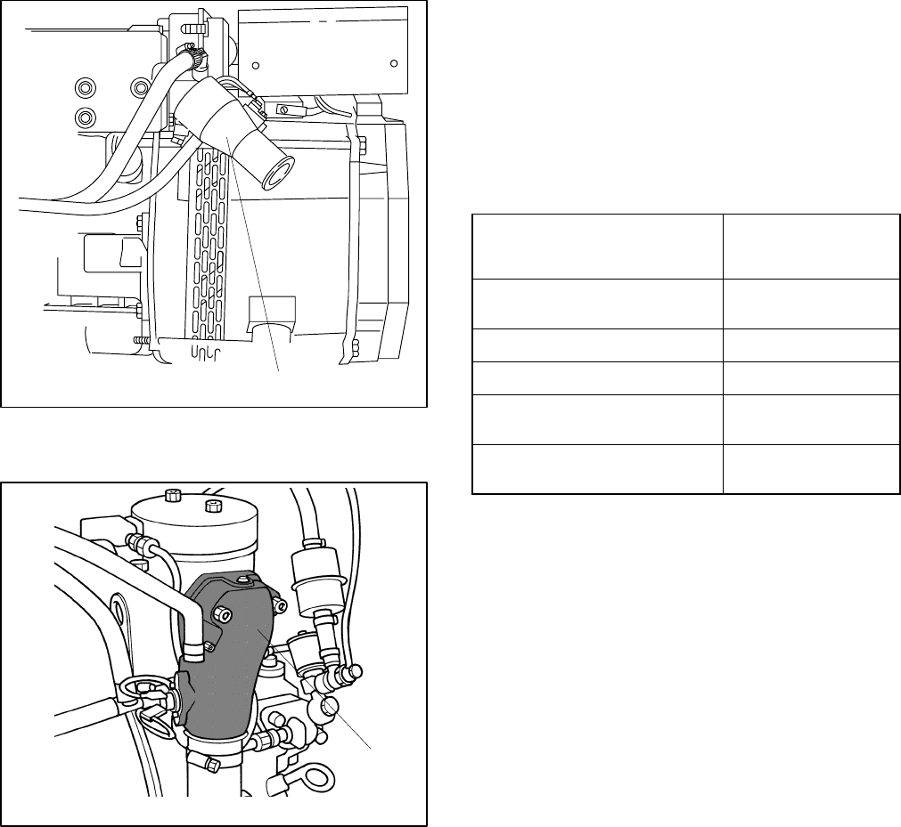
1
TP-6134-
1. Water/exhaust outlet
Figure 4-2 Mixer Elbow/Exhaust Connection,
3.5EFOZ/4EOZ Model Only
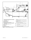
Locate the exhaust outletat least 10 cm (4 in.) abovethe
waterline when the craft is loaded to maximum capacity.
Install an exhaust port with the flap at the exhaust
(transom) outlet to prevent water backup in following
seas or when moving astern (backward). A lift in the
exhaust piping before the piping exits the craft prevents
backwash. See Figure 4-4, item 1. Support the exhaust
lines to prevent the formation of water pockets.
Exhaust system installation guidelines for various
generator set locations follow. Information and
illustrations of stern- (rear) exhaust installations also
apply to side-exhaust installations. Where exhaust lines
require passage through bulkheads, use port (left)- or
starboard (right)- side exhaust outlets, also in
applications in which long exhaust lines to the transom
(rear) could cause excessive back pressure. See
Figure 4-3 for allowable back pressures. Should any
information regarding installation conflict with USCG
Regulations, follow USCG Regulations.
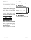
Model
Allowable Exhaust
Back Pressure,
≤
kPa (mm H
2
O)
4/8.5/9/23/27EFOZ and
5/10/28/32EOZ
9.81 (1000)
6.5EFOZ and 8EOZ 11.77 (1200)
11/16/17.5EFOZ and 13/20EOZ 6.37 (650)
3.5/11.5/13/19/20EFOZ and
4/14/15.5/23/24EOZ
4.90 (500)
33/40/55/70/80/100/125EFOZ
and 40/50/65/80/99/125/150EOZ
7.47 (762)
Figure 4-3 Allowable Exhaust Back Pressures
4.3.1 Above-Waterline Installation
Install a customer-supplied silencer with the silencer’s
outlet at a maximum of 3 m (10 horizontal ft.) from the
center of the engine’s exhaust outlet. See Figure 4-4.
Mount a typical silencer with the inlet and outlet
horizontal and with thedrain plug down. Use an exhaust
hose pitch of at least 13 mm per 30.5 cm (0.5 in. per
running foot). Some silencers require two support
brackets or hanger straps for installation to stringers or
other suitable structure. Follow the instructions
provided with the silencer. Install any lift (see
Figure 4-4, item 1) in the exhaust line below the engine
exhaust manifold outlet.