


Operation 15
5WPMAN0862 (11/11/2010)
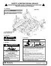
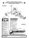
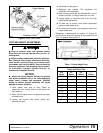
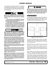
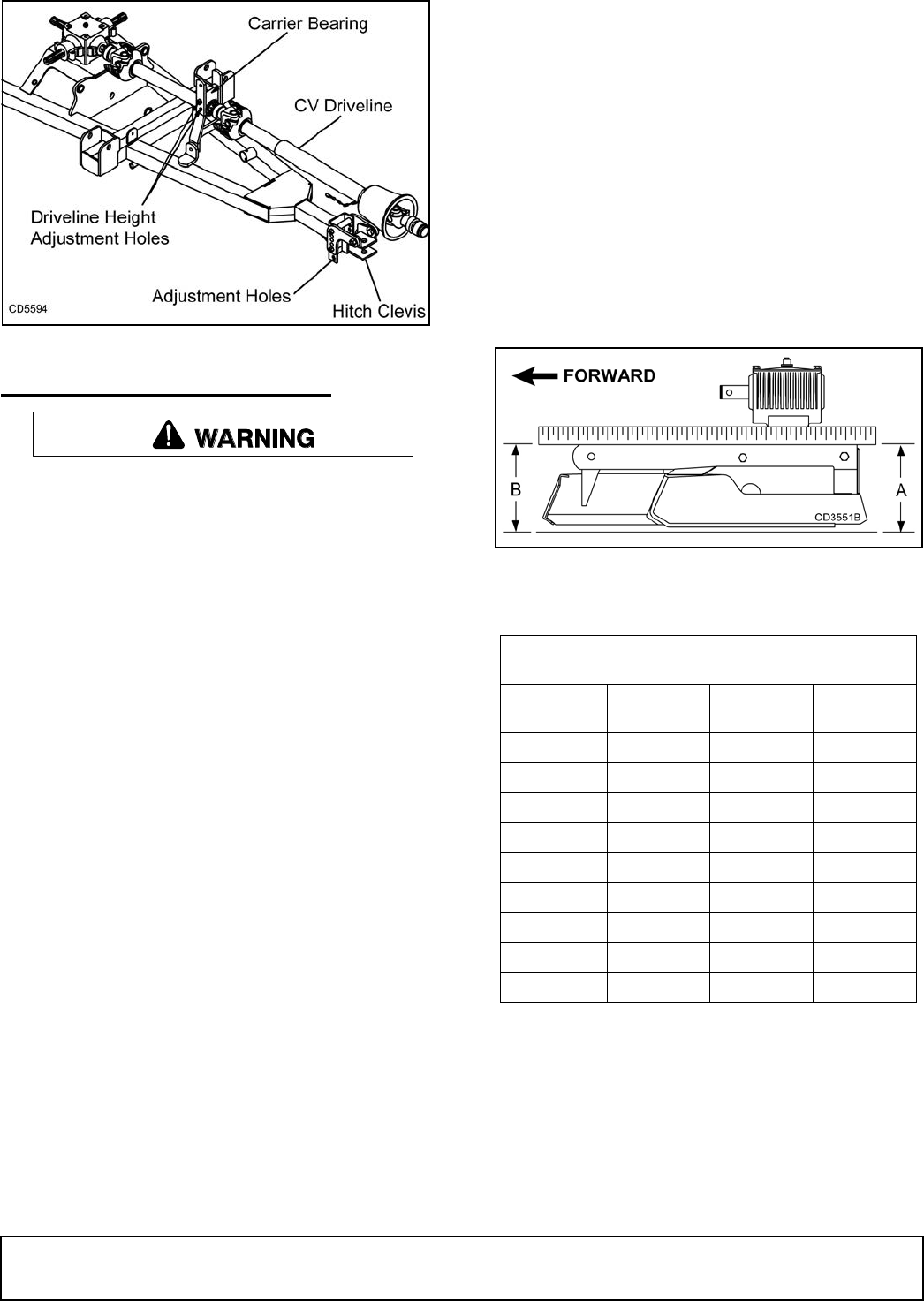
Figure 2. Level Trailer Frame
CUTTING HEIGHT ADJUSTMENT
Keep all persons away from operator control
area while performing adjustments, service, or
maintenance.
Before working underneath, carefully read Oper-
ator’s Manual instructions, disconnect driveline,
raise mower, securely block up all corners with
jackstands, and check stability. Secure blocking
prevents equipment from dropping due to hydrau-
lic leak down, hydraulic system failures, or
mechanical component failures.
NOTICE
■ Avoid low cutting heights. Striking the ground
with blades produces one of the most damaging
shock loads a mower can encounter. Allowing
blades to contact ground repeatedly will cause
damage to mower and drive.
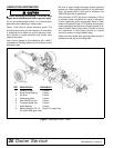
1. Level mower from side to side. Check by
measuring from mower frame to the ground at
each deck rail.
2. Verify that the same amount of spacers are under
all caster arms.
3. Loosen cap screws that attach caster arm
assembly to deck.
4. Set mower on the ground.
5. Retighten cap screws. This equalizes the
clearance in the bolt holes.
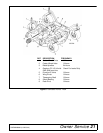
6. Best mowing results will be obtained with front of
mower level with, or slightly lower than, the rear.
7. Cutting height is controlled with front and rear
caster wheel adjustment.
8. To raise rear of mower, move caster adjustment
spacers under caster arms.
9. To raise front of mower, move spacers under front
caster wheel arms.
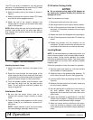
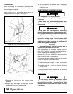
Remember, measurement at location A (Figure 3)
should not be less than location B and should not be
over 1/2" greater than location B
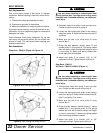
Figure 3. Cutting Height Adjustment
Table 1: Cutting Height Chart
Spacers Required Under
Caster Arm Pivot Tube
Cut
Height
1/2"
Spacer
3/4"
Spacer
1
Spacer
1"
1-1/2" 1
2" 1
2-1/2" 1 1
3" 2
3-1/2" 1 2
4" 1 2 1
4-1/2" 2 2
5" 1 2 2