


14 Operation
5WPMAN0862 (11/22/2010)
The PTO drive shaft is intended for use with tractors
that have 14 inches between the end of the PTO shaft
and the tractor's drawbar hitch pin hole.
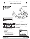
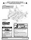
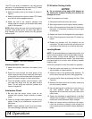
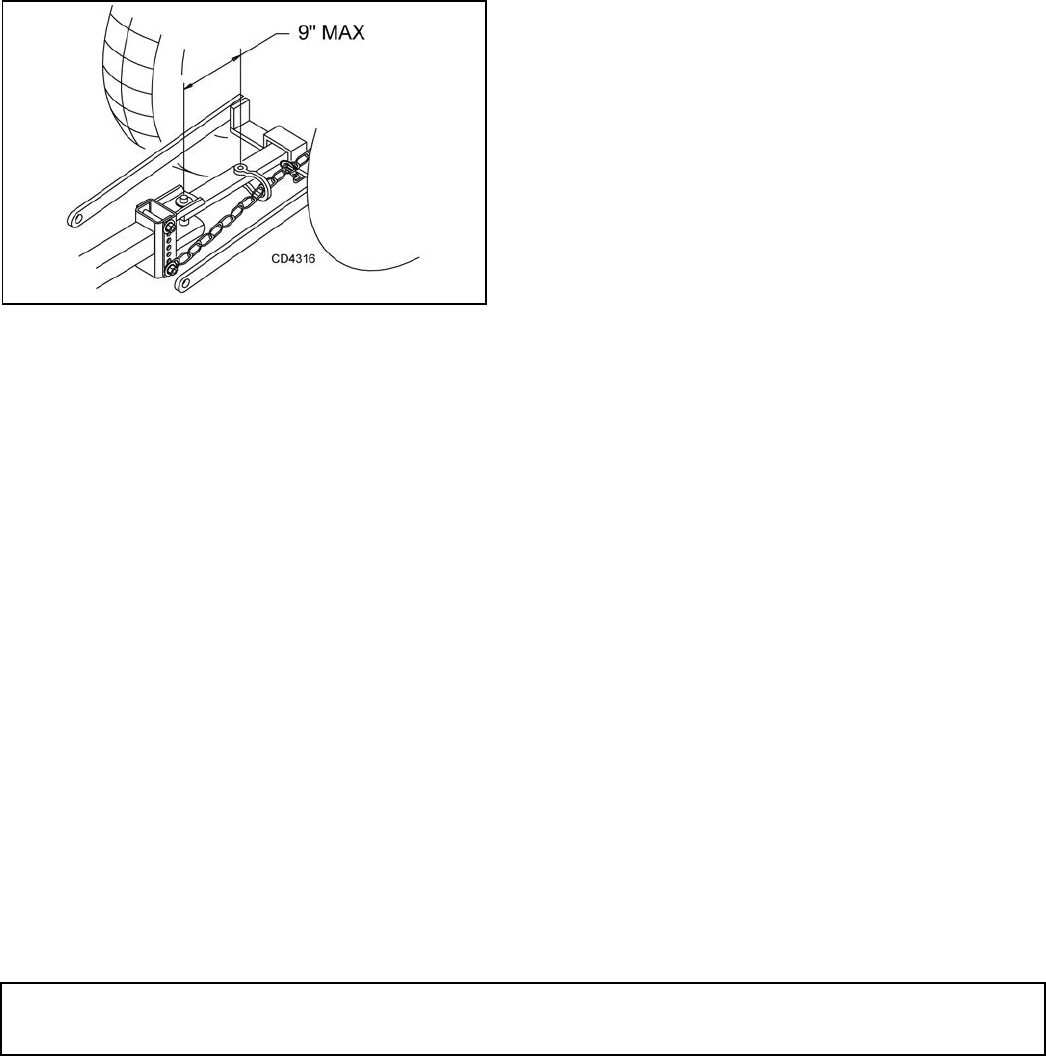
3. Attach the safety chain to the tractor as shown in
Figure 1.
4. Attach the mower drive shaft to tractor PTO. Make
sure the lock collar engages securely.
5. Attach the end of the mower’s transport lock
release rope to a location on the tractor within easy
reach of the operator.
NOTE: When routing the rope, do not route through the
hydraulic hose guide and do not allow rope slack to
drop between the driveline shields and the gearbox
rotating shafts.
Figure 1. Tow Chain Installation
Attaching Hydraulic Hoses
1. Attach the hydraulic hose from the mower to the
tractor.
2. Route the hose through the hose guide of the
trailer frame and be sure the hose can slide freely
in the guide. Do not allow hose slack to drag on the
ground or become caught on tractor protrusions.
3. From the operator position, start the tractor, raise
and lower the wings, and the rear deck several
times. This will purge the hydraulic cylinders and
hoses of trapped air.
Interference Check
1. Be sure that the tractor 3-point arms do not
interfere with hydraulic hoses, driveline or mower
frame.
2. Check for straight ahead operation and full turning
angles. If there is any interference, remove the 3-
point arms.
NOTE: Contact between 3-point arms and mower
can cause damage, especially when turning.
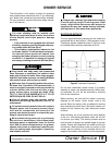
CV Driveline Turning Limits
NOTICE
■ Do not exceed turning angle of 80 degrees at
the head of the Constant Velocity (CV) driveline or
damage will occur.
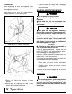
Check for excessive turn angle:
1. Disconnect the driveline from the tractor.
2. Start engine and turn as far right or left as possible.
3. Shut off the engine and connect the CV driveline to
the tractor. If it cannot be connected, the turn angle
is too severe.
4. Restart the tractor and straighten the angle slightly.
5. Shut off the engine and connect the CV driveline to
tractor.
6. Repeat the process until the driveline can be
connected. The point at which the driveline can be
connected is the maximum turn that can be made.
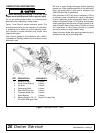
Leveling Mower
NOTE: To ensure satisfactory mower performance, the
trailer frame and decks must be leveled before operat-
ing the mower. During normal operation, the mower
should be leveled twice each season. The mower must
be leveled each time a tractor with a different drawbar
height is used.
Follow this procedure to level the mower for operation:
1. Park the tractor and mower on a flat level surface
with the decks in mowing position.
2. Inflate all tires to the recommended pressure: 70
psi for trailer tires and 30 psi for deck gauge tires.
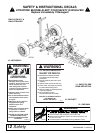
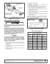
3. Level the trailer frame by adjusting the hitch. (See
Figure 2.)
4. Remove the hitch clevis from the trailer frame and
pin to the tractor drawbar.
5. Use the parking jack to adjust the trailer frame to
the level position. Align the nearest hitch
adjustment hole in the hitch clevis with a hole in the
trailer frame.
6. Tighten the hardware to specifications in the Bolt
Torque Chart on page 61. Readjust the level of the
frame each time the drawbar height changes.
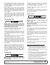
7. Attach the mower and the driveline to the tractor.
Level the driveline by placing a bolt through the
carrier bearing and the driveline height adjustment
holes.