


English - 47
6. MENU FUNCTIONS
• Direction
Specify to the right, left, guide 1 or guide 2
depending on which direction the area lies
from the charging station. The direction is set
looking from the charging station in the
approach direction of the mower.
When a guide wire is installed the direction can
be specified as the guide wire. The mower will
now follow the selected guide wire instead of
the boundary wire.
• Distance
Specify the number of metres along the
boundary wire or guide wire from the charging
station to the place in the remote area where
the mower shall start mowing.
Tip! Use the Test OUT (3-2-5) function (see
page 50) to find out how far it is to the remote
area. The distance, stated in metres, will appear
on the mower display.
• Proportion
Specify a value for how often of the occasions
Automower
®
leaves the charging station it
should follow the loop out to the remote area.
For example the value 20 % means that in 20 %
of the occasions Automower
®
leaves the
charging station, it does it in the direction to the
remote area. In the remaining 80 % of the
occasions the mower leaves the charging
station according to the setting made for its
function Exit angles (3-1).
If a value of 20 % is specified for Area 1 and
10 % for Area 2, the remaining 70 % is allocated
to the selection under Exit angles (3-1).
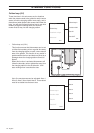
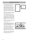
• Follow loop in (3-2-2)
This function is used to control how Automower
®
searches for the charging station.
Automower
®
always starts the search for the
charging station in an irregular search method. In
some gardens this is not sufficient for the mower
to quickly find the charging station. The search
can then be optimised using the Follow loop in
function.
When the mower still can not find the charging
station after a specific period of irregular
searching, it also starts to search for the guide
wires and after a further period also the
boundary wire to follow one of them into the
charging station instead. This time is stated in
minutes, and delays searching for guide 1, guide 2
and the boundary wire.
The delay time can be adapted to the shape of the
garden in the Follow loop in function.
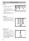
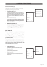
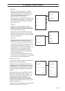
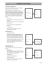
Direction
Distance
Proportion
Area 1
Area 2
Area 3
Area 4
Area 5
Right
Left
Guide 1
Guide 2
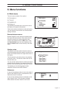
Direction
Distance
Proportion
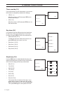
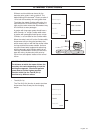
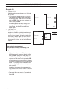
3-2
3-2-2
Exit angles
Follow loop
Installation shape
Advanced
Follow loop out
Follow loop in
Corridor width
Test IN
Test OUT