


ASSEMBLY PROCEDURES
WARNING
Never try to start engine without side case
securely fastened.
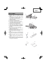
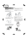
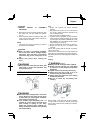
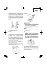
1. Remove chain bar clamp nuts (1).
2. Remove the side case (2) as pinching the rear
part of the side case (2). (Fig. 1)
2
1
Fig. 1
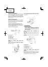
* In case of installing the spiked bumper (3),
install the spiked bumper (3) (if so equipped) to
the unit with two screws. (Fig. 2)
3
Fig. 2
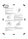
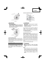
3. Install the chain bar (4) onto the bolts (5), then
push it toward the sprocket (6) as far as it will go.
Make sure that the boss of chain tension adjust
bolt (7) fi ts into the hole of the bar (8). (Fig. 3)
6
4
5
8
7
Fig. 3
NOTE
Slightly move the bar back and forth and make
sure the chain tension boss (7) fi ts into the hole
(8) in the bar properly. (Fig. 3)
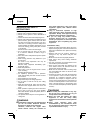
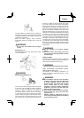
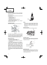
4. Confi rm the direction of saw chain (9) is correct
as in the fi gure, and align the chain on the
sprocket. (Fig. 4)
9
Fig. 4
5. Guide the chain drive links into the bar groove all
around the bar.
6. Install the side case (2) onto the bolts (5).
Then tighten the clamp nuts (1) temporarily.
(
Fig. 1
)
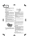
7. Raise the bar end, and tighten the chain (9)
by turning the tension adjustment bolt (10)
clockwise. To check proper tension, lightly lift
up the center of chain and there should be about
0.02 – 0.04 ″ (0.5 – 1.0 mm) clearance between
bar and edge of drive link (11). (Fig. 5, 6)
9
11
10
0.02 – 0.04 ″
(0.5 – 1 mm)
Fig. 5
Fig. 6
8
English