924916KG251004
OPERATING THE MOWER
MK3 200mm FLOATING CUTTERHEAD
1D876P07A
1D876P06B
B
A
D
E
1D876P10A
C
E
=
A
F
1.41
1.41
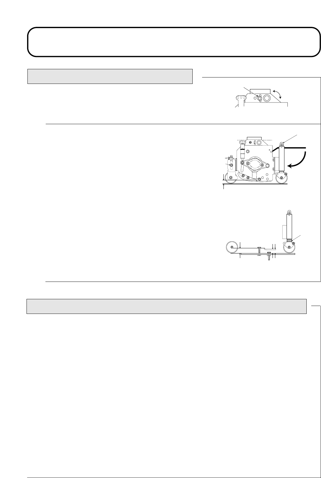
Pivot knuckle fixing: Secure the bolt in the rear “floating” slot posi-
tion ‘A’ as shown.
Height of cut adjustment: The height of cut is gauged by the position
of the front and rear rollers.
To alter the rear roller position, turn the adjusting nut assembly ‘B’ both
ends clockwise to decrease height of cut ‘E’ or anti-clockwise to
increase height of cut ‘E’.
IMPORTANT: PREVENT DAMAGE - Do not attempt to unlock
the nut assemblies, ‘B’.
To alter the front roller position loosen bolts ‘F’. Release and turn
adjusting nuts ‘D’ both ends clockwise to increase the height of cut or
anti-clockwise to decrease the height of cut.
Ensure that all cutterheads are set at the same height of cut by referring
to the indicator rings ‘C’ or use the height of cut gauge across the full
width of each cutterhead as shown.
Tighten nuts ‘D’ and ‘F’ both ends.
CENTRE CUTTERHEAD HEIGHT OF CUT CORRECTION ADJUSTMENT
With all cutterheads set at the same HOC via the indicator rings, it may be noticeable that the centre unit pro-
duces a higher cut finish compared to the wing units. The centre unit is pulled and the wing units are pushed
this presents marginally different cutting angles relative to the ground. The amount of HOC variation, which
results from this will be influenced by the terrain but satisfactory results can usually be achieved by setting the
centre cutterhead HOC indicator ring lower than the wing unit settings.


