12
40" MOWER
Fi
g
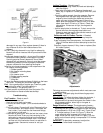
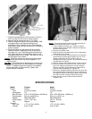
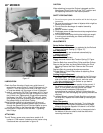
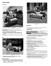
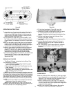
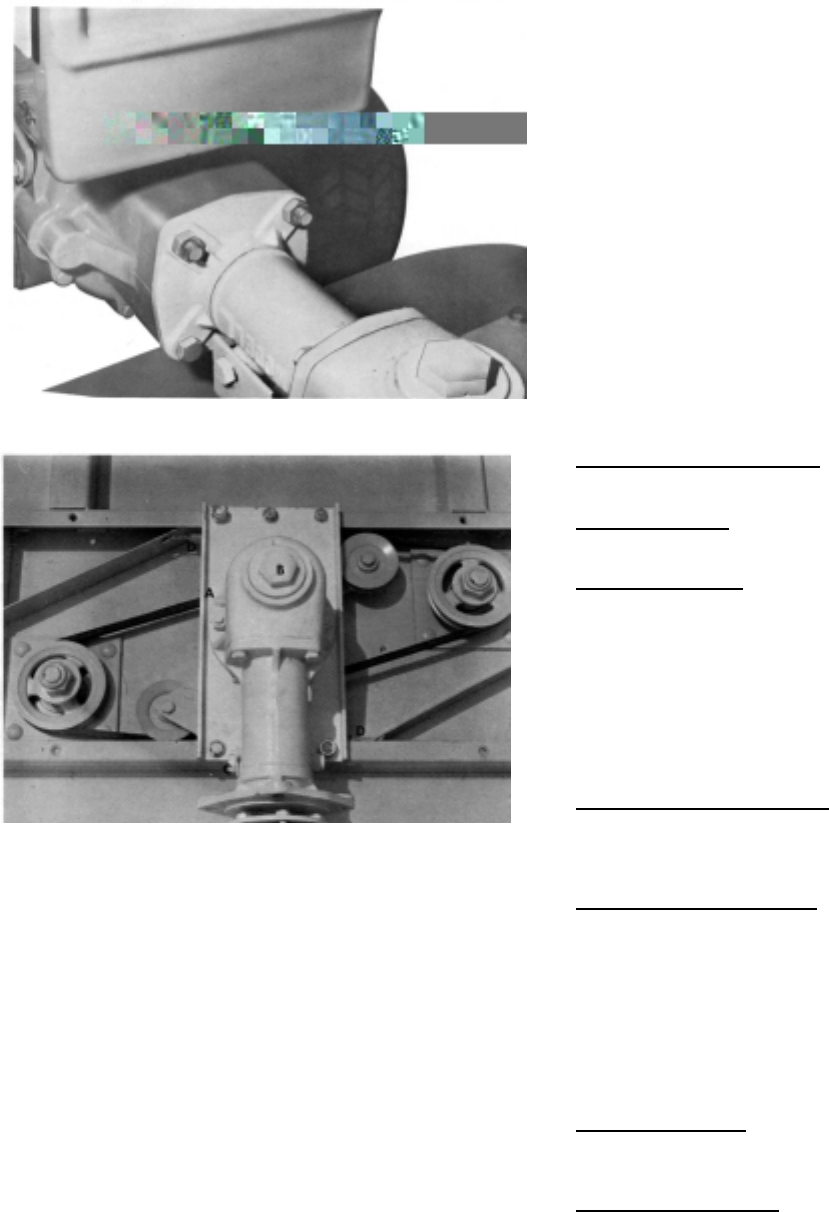
ure 16
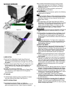
Figure 17
LUBRICATION
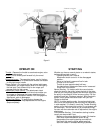
Check the Gear Housing oil level every eight hours of
operation by removing the Oil Level Plug shown at A in
Figure 17. If oil runs out, the oil level is all right, if not,
oil must be added until the proper oil level is obtained.
To add oil, remove the Oil Filter Plug shown at B in Figure
17, and pour through the hole until oil begins to run out
the oil level hole. Replace both Plugs before operating
the Mower. Use SAE 140 or 90W EP lubricant. Use a
good grade of general purpose grease occasionally in
the grease fitting of the Swivel Casting.
Blade spindles should be lubricated every 8 hours of
service with general purpose grease. Apply lubricant
through the grease fitting until lubricant starts to come
out the vent hole on the opposite side of the spindle.
No lubrication is required for the two Belt - Tightening
Idler Pulleys.
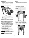
ATTACHING
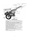
The 40" Rotary mower cuts a maximum swath of 40
inches or 1.006 meters. It attaches to the tractor using
2 bolts and two nuts as shown in figure 16.
CAUTION
When attaching, be sure the Engine is stopped, and the
Attachment Clutch Control is at the "OUT" position and
the operating levers are in the neutral position.
SAFETY PRECAUTIONS
1. Do not let anyone operate the machine until he has had proper
instructions.
2. Be sure the work area is clear of objects which might be
picked up and thrown.
3. Do not direct the discharge of material toward by
standers.
4. Keep all shields in place.
5. Disengage power to attachment and stop engine before
making adjustments.
6. Do not wear loose fitting clothing that might get caught
in moving parts and keep your hands and feet away
from moving parts.
ADJUSTMENTS
Swivel Action Adjustment
The Swivel actions the Mower is regulated by the Bolt and
Nut on the Swivel Casting (C, Figure 17).
Belt Adjustment
None required. Belts are tensioned automatically by
spring-loaded Idlers.
Belt Replacement
Remove both Belt Covers.
Detach one end of each Idler Tension Spring (D, Figure
17).
Remove Belts from around Rotor Pulley and Idler Pulleys.
Remove the two Nuts and three Bolts holding the Drive
Mounting Plate to the Deck. Remove the Drive and
Belts.
Replace Belts by reversing the above procedure.
Put new Belts on Drive Pulley before re-attaching Drive
Plate to Mower.
Cutting Height Adjustment
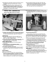
The cutting height o e Mower is adjusted by the Collars on
the Rotor Shaft. The closer the Blades are to the under
side of the Deck, the higher the cut, and vice versa.
Vary the combination of the Collars as you desire.
Caster Wheel Adjustment
Caster Wheels keep the Mower parallel to the ground. If
the Mower cuts closer on one side than it does on the
other, or if the Skids mark the ground, the Caster
Wheels should be adjusted. Adjustment is
accomplished by removing "Hairpin" Cotters from the
top of the fork, and rearranging the Spacing Washers as
required.
To replace Wheels, remove Elastic Stop Nut and remove
the Axle Bolt, replace with new Wheel by reversing the
procedure.
Blade Sharpening
Use a grindstone to sharpen the blade. Try to follow the
same bevel as the originally sharpened cutting edge,
although the precise degree of the bevel is not critical.
Removing the Blades
Use a standard 3/8 inch socket drive in the square hole in
the bottom of the rotor shaft to hold the shaft while
removing the blade nut.


