10
ATTACHMENT OPERATING INSTRUCTIONS
30" ROTARY MOWER
Fi
g
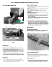
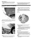
ure 10
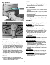
Figure 11
LUBRICATION
Use SAE 140 or 90W EP gear lubricant in the Gear
Housing. Use General Purpose Grease occasionally in
the Gear Fitting of the Swivel Casting.
Check the Gear Housing oil level every eight hours of
operation by removing the Oil Level Plug (Figure 11). If
oil runs out, the oil level is all right, if not, oil must be
added.
To add oil, remove the Oil filler Plug, (Figure 11 ), and
pour through the Oil Filler Hole until oil begins to run out
the Oil Level Hole. Replace both plugs before operating.
ATTACHING
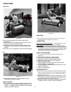
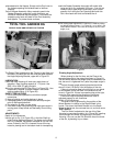
The 30" Rotary Mower cuts a maximum swath of 30
inches or 76.2 centimeters and is attached to the tractor
using two Nuts and two Bolts. See Figure 10.
Cutting Height Adjustment
Cutting height is adjusted by the Collars on the Rotor
Shaft. The closer the Blade is to the Gear Housing, the
higher the cut, and vice versa.
Blade Sharpening
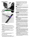
Use a grindstone to sharpen the Blade. Try to follow the
same bevel as the originally-sharpened cutting edge,
although the precise degree of bevel is not critical.
Figure 12
SAFETY PRECAUTIONS
I. Do not let anyone operate the machine until he has had
proper instructions.
2. Be sure the work area is clear of objects which might
be picked up and thrown.
3. Do not direct the discharge of material toward by-
standers.
4. Keep all shields in place.
5. Disengage power to attachment and stop motor before
making adjustments.
6. Do not wear loose fitting clothing that might get caught
in moving parts and keep your hands and feet away
from moving parts.
7. Never operate the Mower unless the Front Fender or
optional Chain Guard is on the front of the Mower, and
the Rear Fender is on the rear.
8. WHEN USING THE 30-INCH ROTARY MOWER,
NEVER SHIFT THE INSIDE OPERATING LEVER
DIRECTLY FROM HIGH TO LOW. ALWAYS PAUSE
MOMENTARILY IN NEUTRAL, GIVING THE BLADE A
CHANCE TO SLOW DOWN NATURALLY, THUS
AVOIDING THE SEVERE BRAKING ACTION FROM A
SUDDEN SHIFT INTO LOW GEAR.
ADJUSTMENTS
Swivel Action Adjustment
Swivel action of the Drive Assembly is regulated by the
Swivel Adjustment Bolt and Nut, (Figure 11 ).
Loosening the Adjustment Nut frees swivel action;
tightening it restrains swivel action.


