


GB - 24
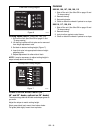
REMOVE SINGLE LEVER PLATE (988105,
106, 107, 108, 109, 113)
Without the single lever plate, the speed control levers
can work separately to adjust tracking on uneven
terrain.
To remove:
1. Remove knobs from speed control levers.
2. Remove and keep single lever plate.
3. Remove and keep nuts.
4. Apply Loc-Tite 495 (or equivalent) to knob
threads.
5. Replace knobs on speed control levers.
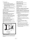
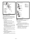
REPLACING THE HYDRO PUMP BELT
1. Place speed control levers in neutral position
(988105, 106, 107, 108, 109, 113).
2. Remove mower belt from mower clutch sheave
(Figure 19).
3. Remove pump belt idler spring from eye bolt.
4. Remove belt from engine sheave and pump
pulleys.
5. Install new belt on engine sheave and pumps.
6. Reconnect idler spring to idler.
7. Put mower belt back on mower clutch sheave.
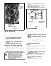
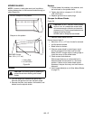
CLUTCH ADJUSTMENT
If clutch fails to engage or disengage properly or
begins to make abnormal noise, check the air gap
adjustment at the three inspection slots.
To check:
1. Stop engine, remove key and wait for all hot parts
to cool.
2. Measure the air gap between the armature and
the rotor.
Minimum: A .005" feeler gauge should slide
between armature and rotor with slight contact.
Maximum: A .023" feeler gauge should slide
between armature and rotor with slight contact.
3. Repeat for each inspection slot.
To adjust:
1. If necessary, loosen gap adjustment nuts until a
.005" feeler gauge fits between armature and
rotor.
2. Slide a .012" feeler gauge between armature and
rotor.
3. Tighten gap adjustment nut until there is slight
contact on feeler gauge.
4. Repeat steps 1 – 3 at each inspection slot.
NOTE: Adjust air gap as evenly as possible.
5. Start unit, engage and disengage PTO.
6. Shut off unit.
7. Recheck air gap and adjust if needed.
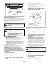
WARNING: An extension spring, when
extended, stores energy and can be
dangerous. Always use tools specifically
designed for installing or removing an
extension spring. Always compress or
extend springs slowly.
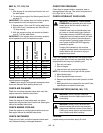
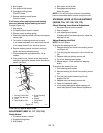
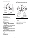
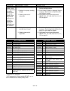
Figure 18
1. Neutral Bracket
2. Clevis
3. Speed Control Arm
1
4
2
3
Connect clevis
here for faster
speed range.
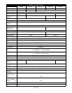
Figure 19
OG0795
1. Mower Clutch
Sheave
2. Mower Belt
3. Pump Belt Idler
Spring
4. Hydro Pump Belt
5. Pump Pulleys
1
2
3
4
5