


GB - 23
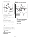
SPEED RANGE ADJUSTMENT (988105,
106, 107, 108, 109, 113)
The steering levers control travel speed. The unit can
be adjusted from a slower to a faster speed range.
NOTE: Setting the unit to the faster speed range will
make the steering controls more sensitive.
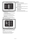
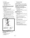
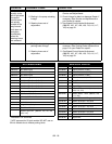
To adjust (Figure 17):
1. Stop engine.
2. Put speed control levers in neutral.
3. Remove pump actuating spring from speed
control plate.
4. Remove pump actuating spring anchor from
speed control plate. Keep hardware.
5. Remove steering control rod clevis from speed
control plate.
6. Move the steering control rod clevis to the other
hole in the speed control plate and secure with
clevis pin and hairpin as shown.
7. Install actuating spring anchor in the open hole.
8. Remove the actuating spring anchor from the
frame.
9. Attach the actuating spring anchor to the hole in
frame as shown.
10. Replace pump actuating spring.
11. Tighten the nuts holding the speed control levers
in place (if necessary).
12. Repeat procedure on other steering control lever.
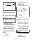
988116, 117, 120, 314
NOTE: Setting the unit to the faster speed range will
make the steering controls more sensitive.
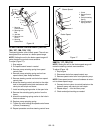
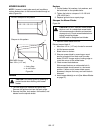
To adjust (Figure 18):
1. Stop engine.
2. Disconnect clevis from speed control arm.
3. Remove speed control arm from hydraulic pump.
NOTE: Save speed control arm and hardware to return
unit to slower speed range.
4. Connect clevis to return to neutral bracket on the
hydraulic pump with clevis pin and hairpin.
5. Repeat steps 1 - 4 for the other pump.
6. Check and adjust tracking as needed.
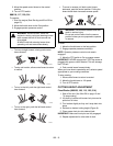
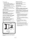
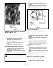
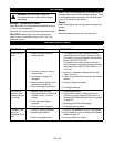
Figure 16
OG1370
1. Steering
Control Lever
2. Steering Link
Rod
3. Jam Nut
4. Steering Link
Clevis
5. Steering
Control Rod
1
2
3
4
5
Faster Speed
Slower Speed
Figure 17
1. Clevis
2. Speed Control
Plate
3. Pump Actuating
Spring
4. Pump Actuating
Spring Anchor
1
2
3
4
1
2
3
4
OG1340
3
3