


GB - 10
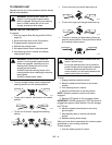
ALWAYS keep body and hands away from pin holes or
nozzles which eject hydraulic fluid under pressure.
Allow hot parts to cool.
ALWAYS block wheels, engage parking brake and
know all jack stands are strong, secure and will hold
weight of unit during maintenance.
An extension spring, when extended, stores energy
and can be dangerous. Always use tools specifically
designed for installing or removing an extension spring.
Always compress or extend springs slowly.
ALWAYS maintain unit in safe operating condition.
Damaged or worn out muffler can cause fire or
explosion.
Keep hardware, especially blade attachment bolts,
tight.
Maintain or replace safety and instruction labels, as
necessary.
For unit storage or extended storage:
• NEVER store with fuel in fuel tank, inside a
building where any ignition sources are present.
• Allow engine to cool completely.
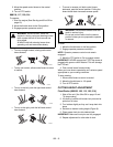
Use only attachments or accessories designed for your
unit and that can be used safely on your terrain.
Check attachment components frequently for wear,
damage or deterioration. Replace with manufacturer’s
recommended parts for safety.
To reduce fire hazard and overheating, keep equipment
free of grass, leaves, debris or excessive lubricants.
Use extra care with grass catchers and other
attachments. These can change the stability of the unit.
Use only approved hitch points.
ALWAYS be aware of attachments when turning.
ALWAYS allow adequate clearance between
attachments, personnel, and other objects.
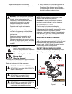
1. Remove the unit from shipping container.
2. Adjust tire pressure to 8 to 16 psi (55 to 110 kPa).
3. Service and connect battery.
See Charge Battery
on page 25
.
4. Check the adjustments outlined in
Service &
Adjustments
.
5. Check engine oil level. See engine manual.
6. Check hydraulic fluid level. See
Maintenance
.
7. Add clean fuel to the fuel tank. See engine
manual for type and grade.
8. Check for loose hardware.
9. Be sure that safety interlock system operates
correctly. See
Check Safety Interlock System
on
page 17.
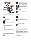
10. Be sure that unit tracks straight.
Unit must not pull sharply to the left or right when
the speed control levers are pushed quickly
forward.
Unit must not pull sharply to the left or right when
the steering levers are released. See
Adjusting
the Unit to Track Straight
on page 20.
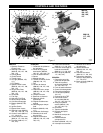
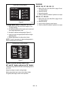
CONTROLS AND FEATURES
Safety Interlock System
The engine will only start with the PTO disengaged, the
speed control levers in neutral and the parking brake
on.
Operator Presence Control (988105, 106, 107,
108, 109, 113)
The operator presence control lever must be
depressed to operate the PTO. When the speed control
levers are in forward position, the parking brake is off,
or the PTO is engaged, releasing the operator
presence control lever stops the engine.
NOTE:
Moving the speed control levers out of neutral
with the parking brake engaged will shut down the
engine. PTO must be off and parking brake must be on
to keep engine running when operator presence con-
trol is released.
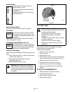
Operator Presence Control
(988116, 117, 120, 314)
The operator presence control levers must be
depressed to operate the PTO. When the PTO is
engaged, releasing the operator presence control
levers stops the mower blades.
ASSEMBLY
WARNING:
AVOID INJURY. Read and
understand the entire
Safety
section before
proceeding.
OPERATION
WARNING:
AVOID INJURY. Read and
understand the entire
Safety
section before
proceeding.
DANGER:
SAFETY INTERLOCK SYSTEM
FAILURE and improper operation of unit can
result in death or serious injury. ALWAYS
know the safety interlock system is operating
properly. See
Check Safety Interlock System
on page 17 for testing instructions.