


GB - 22
4. Start engine.
5. Run engine at full throttle.
6. Disengage parking brake.
Check for creep.
7. Release steering control levers.
Check for creep.
If unit creeps when parking brake and steering
levers are released: Adjust steering rod clevis.
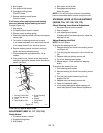
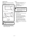
To adjust (Figure 15):
1. Stop engine.
2. Put speed control levers in neutral.
3. Remove pump actuating spring.
4. Disconnect steering control rod clevis from speed
control plate.
5. Turn clevis on steering control rod to adjust.
If unit creeps backward, turn clevis down the rod.
If unit creeps forward, turn clevis up the rod.
6. Replace steering control rod clevis, clevis pin,
hairpin and pump actuating spring.
7. Check adjustments and repeat steps 1-6 as
needed.
8. Once neutral is set, loosen neutral stop bracket
and slide it against the washer above the steering
control rod clevis.
CONTROL LEVER NEUTRAL
ADJUSTMENT (988116, 117, 120, 314)
Check Neutral
1. Put control levers in neutral.
2. Engage parking brake.
3. Start engine.
4. Run engine at full throttle.
5. Disengage parking brake.
Check for creep.
NOTE: If unit will not return to neutral, immediately
have an authorized dealer service or adjust the unit.
STEERING LEVER LATCH ADJUSTMENT
(988105, 106, 107, 108, 109, 113)
Check Steering Lever Neutral Adjustment
1. Set speed control levers to neutral.
2. Shut off engine.
3. Lock steering lever latches.
If latches cannot lock steering levers, adjust the
steering link rod.
Adjust Steering Link Rod
NOTE: Shut off engine.
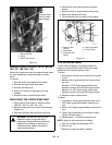
To shorten the steering link rod:
1. Remove steering link clevis from steering control
rod (Figure 16).
2. Turn clevis up the steering link rod to shorten the
link.
3. Replace clevis on steering control rod.
4. Try to lock steering lever latches.
5. Repeat steps 1-3 until latches lock steering
levers.
To lengthen the steering link rod:
1. Lock steering lever latches.
2. Remove steering link clevis from steering control
rod.
3. Turn the clevis down the steering link rod
lengthen the link.
4. Replace clevis on steering control rod.
5. Check for backwards creep.
6. If unit creeps backwards, adjust steering rod
clevis (see Speed Control Neutral Adjustment).
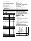
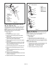
Figure 15
1. Steering Control Rod
2. Neutral Stop Bracket
3. Clevis
4. Speed Control Plate
5. Pump Actuating
Spring
6. Washer
7. Flange Nuts
8. Spring
1
2
3
4
5
OG1361
6
7
8