


GB - 21
Check Reverse Tracking (988116, 117, 120,
314)
1. Adjust forward tracking (See Check Forward
Tracking on page 20).
2. Slowly pull both control levers all the way back.
3. Note which direction, if any, the unit pulls.
4. Stop unit and engine.
5. Adjust tracking if needed.
If unit turns to the right:
1. Reduce the air pressure in the left tire.
2. Increase the air pressure in the right tire.
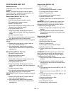
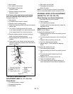
3. Turn the reverse stop bolt on the right neutral
adjustment bracket counterclockwise to speed up
the right wheel.
4. Check reverse tracking and adjust as needed.
If unit turns to the left:
1. Reduce the air pressure in the right tire.
2. Increase the air pressure in the left tire.
3. Turn the reverse stop bolt on the right neutral
adjustment bracket clockwise to slow down the
right wheel.
4. Check reverse tracking and adjust as needed.
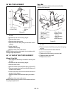
PARKING BRAKE ADJUSTMENT
To check:
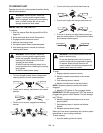
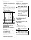
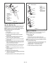
1. Pull back parking brake lever (Figure 12).
Brake arm must contact tire and brake lever must
press brake switch, and there must be an 1/8"
(3 mm) gap between the parking brake arm and
the stop bolt on the unit frame.
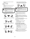
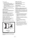
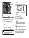
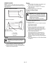
2. Push lever forward (Figure 13).
Brake arm must disengage.
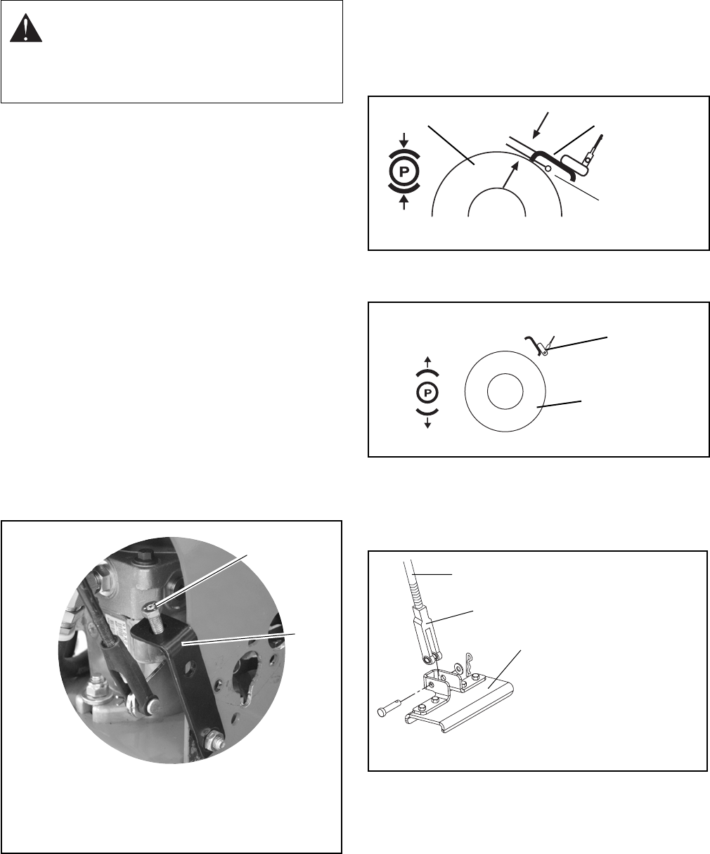
To adjust:
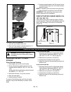
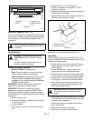
1. Remove clevis from brake arm tab (Figure 14).
2. Turn clevis up or down the brake rod as needed.
3. Replace clevis on brake arm tab.
SPEED CONTROL NEUTRAL
ADJUSTMENT (988105, 106, 107, 108, 109,
113, 116, 117, 120)
Check Neutral
1. Put speed control levers in neutral.
2. Lock steering control levers in neutral.
3. Engage parking brake.
WARNING: Uncontrolled reverse travel can
result in serious injury.
Do not put control levers into the reverse
position unless you are prepared to operate
in reverse.
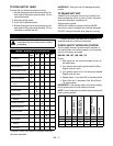
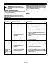
Figure 11
1. Reverse Stop Bolt
2. Neutral Adjustment Bracket
1
2
Parking Brake Arm
Tire
Figure 12
OG1470
Stop Bolt
1/8" (3 mm)
Parking Brake Arm
Tire
Figure 13
OG1470
Figure 14
1. Parking Brake Rod
2. Clevis
3. Parking Brake Arm
1
2
3