


GB - 20
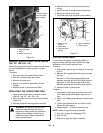
Hydraulic Run-In Procedure
1. Jack the drive wheels off the floor.
2. Start unit. Run engine at slowest speed for 1-2
minutes to bleed hydraulic pumps.
3. Increase engine speed to half. Set speed control
1/3 forward. Run engine for 3-5 minutes to bleed
hydraulic motors.
NOTE: If necessary, start the motors turning by hand.
4. Shut off engine and lower the unit to the floor.
IMPORTANT: If any squealing noise occurs in the
motors, repeat the run-in procedure.
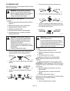
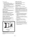
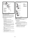
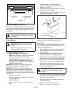
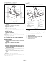
PUMP ACTUATING LINKAGE (988105, 106,
107, 108, 109, 113)
Clean debris from pump actuating linkage to ensure
smooth operation. Clean rust from sliding pins with fine
emery cloth and apply a thin coat of oil to lubricate
(Figure 10).
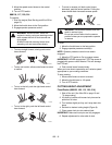
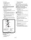
ADJUSTING THE UNIT TO TRACK
STRAIGHT
Check Forward Tracking
1. Start engine and run unit at full throttle.
2. Slowly release both steering levers to the full
outward position (988105, 106, 107, 108, 109,
113).
Slowly push both control levers against the pivot
bar (988116, 117, 120, 314).
3. Note which direction, if any, the unit pulls.
4. Stop unit and engine.
5. Adjust tracking if needed.
Try each of the following steps until the unit tracks
straight. It may not be necessary to perform all the
steps.
If unit turns to the right:
1. Set speed control levers to neutral (see Speed
Control Neutral Adjustment (988105, 106, 107,
108, 109, 113, 116, 117, 120) on page 21).
2. Reduce the air pressure in the left tire.
3. Increase the air pressure in the right tire.
4. Adjust the clevis on the right steering control rod
down the rod.
If unit turns to the left:
1. Set speed control levers to neutral (see Speed
Control Neutral Adjustment (988105, 106, 107,
108, 109, 113, 116, 117, 120) on page 21).
2. Reduce the air pressure in the right tire.
3. Increase the air pressure in the left tire.
4. Adjust the clevis on the left steering control rod
down the rod.
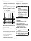
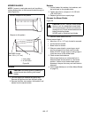
Figure 9
Sliding Pin
Figure 10
Pump Actuating
Linkage
Pump
SERVICE AND ADJUSTMENTS
WARNING: AVOID INJURY. Read and
understand the entire Safety section before
proceeding.