


Generac
®
Power Systems, Inc. 7
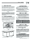
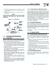
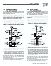
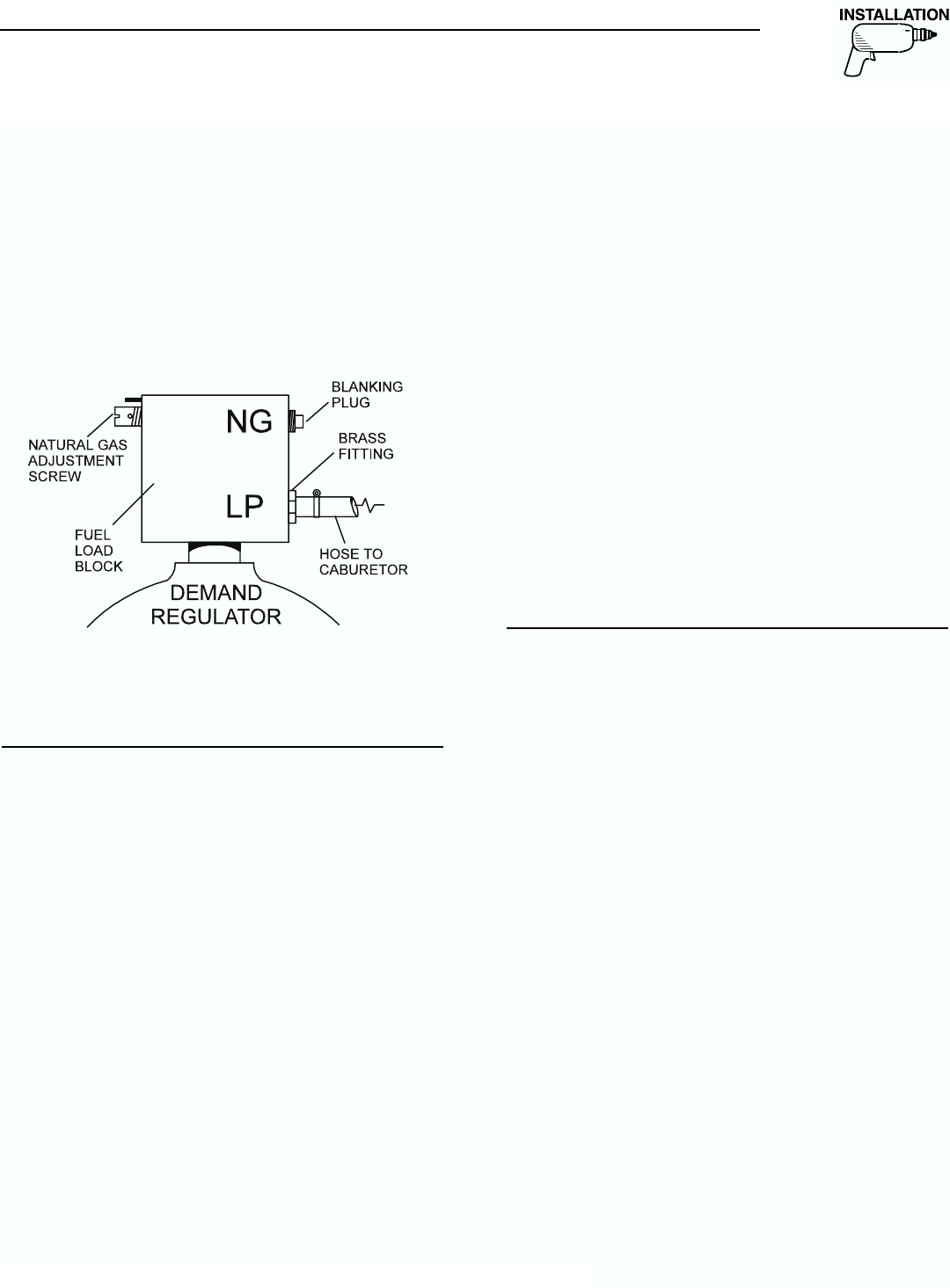
3. Refit the fitting and hose to the LP port and
the blanking plug to the natural gas port
(Figure 1.3).
4. Reverse the procedure to convert back to
natural gas.
NOTE:
The natural gas adjustment screw is preset during
installation and should not need any further
adjustment.
Figure 1.3 – LP Gas Setup
1.7 LOCATION AND MOUNTING
1.7.1 GENERATOR
Install the generator set, in its protective enclosure,
outdoors, where adequate cooling and ventilating air
always is available. Consider these factors:
• Install the unit where air inlet and outlet openings
will not become obstructed by leaves, grass, snow,
etc. If prevailing winds will cause blowing or drift-
ing, you may need to consider using a windbreak
to protect the unit.
• Install the generator on high ground where water
levels will not rise and endanger it.
• Allow sufficient room on all sides of the generator
for maintenance and servicing. A good rule is to
allow 3 feet of space on all sides.
• Where strong prevailing winds blow from one
direction, face the generator air inlet openings into
the prevailing winds.
• Install the generator as close as possible to the
transfer switch. This reduces the length of wiring
and conduit.
• Install the generator as close as possible to the fuel
supply, to reduce the length of piping. HOWEVER,
REMEMBER THAT LAWS OR CODES MAY REG-
ULATE THE DISTANCE.
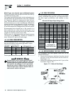
1.7.1.1 6 kW, 8 kW and 10 kW Units (Non-SA)
These Guardian units are supplied with their own
mounting pads and DO NOT require a concrete pad.
Remove the packing material from the unit and unbolt
the two 4-inch by 4-inch wooden blocks from the
underside of the mounting base. Plug the holes with the
plugs provided. Prepare the installation site to accept
the mounting base. Provide adequate substrate to give
sufficient drainage, i.e., a 3-inch deep section of pea
gravel scattered under the mounting base.
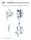
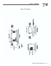
See Figure 1.4 (Pages 8-9) for generator and transfer
switch major dimensions.
1.7.1.2 Sound Attenuated Units
Retain the generator compartment to a concrete slab
with 1/4-inch masonry type anchor bolts. Be sure the
bolts are long enough to retain the compartment. The
slab should be at least 3 inches thick and should
extend beyond the enclosure to a distance of at least
3 inches on all sides.
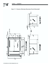
See Figure 1.5 (Page 10) for generator major
dimensions.
1.7.2 TRANSFER SWITCH
1.7.2.1 6 kW, 8 kW and 10 kW Units (Non-SA)
The transfer switch shipped with this generator is
enclosed in a NEMA 1 enclosure. This type of enclo-
sure is intended for indoor use only. Follow these
rules:
• Install the transfer switch indoors on a firm, stur-
dy supporting structure.
• To prevent switch distortion, level the switch
if necessary. This can be done by placing
washers between the switch enclosure and
mounting surface.
• Never install the switch where water or any corro-
sive substance might drip onto the enclosure.
• Protect the switch at all times against excessive
moisture, dust, dirt, lint, construction grit and
corrosive vapors.
1.7.2.2 Sound Attenuated Units
All sound attenuated models have a transfer switch
built into the enclosure and do not require a separate
switch attachment.
◆
◆
Section 1 — Installation
Guardian Air-cooled Generators