


Generac
®
Power Systems, Inc. 25
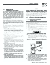
3.7.3 SOUND ATTENUATED UNITS
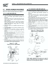
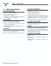
1. Carefully inspect the governor anti-lash
spring (Figure 3.3). Be sure it is not broken
or disengaged.
2. Loosen the governor clamp nut. Then, push the
spring end of the governor lever all the way up
(wide open throttle).
3. Hold the governor lever at wide open throttle and
insert the tip of a screwdriver into the slotted end
of the governor shaft.
• Hold the governor lever at wide open throttle and
rotate the governor shaft fully counterclockwise.
• Hold the governor shaft fully counterclockwise
and tighten the governor clamp nut to 70 inch-
pounds (8 N-m) torque.
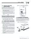
Figure 3.3 – Sound Attenuated
Engine Governor Adjustment
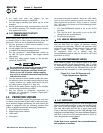
3.8 VOLTAGE REGULATOR
ADJUSTMENT
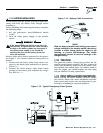
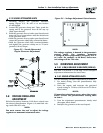
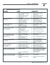
With the frequency between 61-62 Hertz, slowly turn
the slotted potentiometer (Figure 3.4) until line volt-
age reads 244-252 volts.
NOTE:
You must remove the roof to adjust the voltage
regulator on nonsound attenuated units.
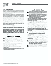
Figure 3.4 – Voltage Adjustment Potentiometer
NOTE:
The voltage regulator is housed in the generator's
control panel. The regulator maintains
a voltage in direct proportion to frequency at a 2-
to-1 ratio. For example, at 62 Hertz, line-to-neu-
tral voltage will be 124 volts.
3.9 OVERSPEED ADJUSTMENT
3.9.1 6 KW, 8 KW AND 10 KW UNITS (NON-SA)
See item 3 of Section 1.15 on Page 15 for overspeed
adjustment information for these units.
3.9.2 SOUND ATTENUATED UNITS
Use the following overspeed adjustment procedure:
1. For initial setting, turn the potentiometer fully
clockwise.*
2. Start the engine and increase the governed
speed setting to 72 Hertz (62 Hertz for 50 Hertz
rated units).
*NOTE:
If immediate shutdown occurs when the engine
starts, reverse the potentiometer setting done
in item 1.
3. Turn the adjustment potentiometer slowly until
the engine shuts down.
4. Readjust the governor to the rated speed.
◆
◆
◆
Section 3 — Post-installation Start-up Adjustments
Guardian Air-cooled Generators