


2.5.3.1 Approximate Crank Cycle Times
• 15 seconds ON
• 15 seconds OFF
• 7 seconds ON
• 7 seconds OFF
• Repeat for 45 seconds
Approximately 90 seconds total
2.5.4 OVERSPEED
This feature protects the generator from damage by
shutting it down if it happens to run faster than the pre-
set limit. This protection also prevents the generator
from supplying an output that could potentially damage
appliances connected to the generator circuit. The over-
speed feature will activate as follows:
1. If the generator runs at 72 Hertz for five seconds,
the generator will shut down.
2. If the generator reaches 75 Hertz, it will shut
down instantly.
2.6 ADDITIONAL GENERATOR
FEATURES
2.6.1 6 KW, 8 KW AND 10 KW UNITS (NON-SA)
The standard 6 kW, 8 kW and 10 kW air-cooled
Guardians offer additional features that are not
factory preset:
1. Remote Start – This allows for remote starting of
the generator by means of the #183 (common)
and #178 (normally open) lines with the
Auto/Off/Manual switch set to AUTO. Closure of
the circuit starts the unit; opening of the circuit
stops the unit. See Figure 2.5.
NOTE:
This function will work ONLY with the unit in the
AUTO mode.
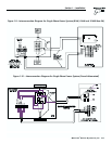
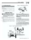
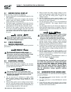
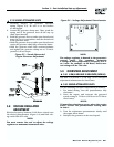
Figure 2.5 – Remote Start/Alarm Options
–Type 14 AWG wire is recommended.
–These options should be wired to the unit by a qualified electrician or
Generac/Guardian Authorized Dealer.
2. Remote/Common Alarm – This allows for an
alarm, light, horn, etc., to activate when any fault
has occurred. Lines #210 (common) and #211
(normally open) provide a “closure” on common
fault, which can be used for 120 volts, 10 amps
maximum. See Figure 2.5.
3. Remote Not Auto – The generator will not auto-
matically start during a utility failure.
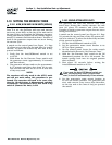
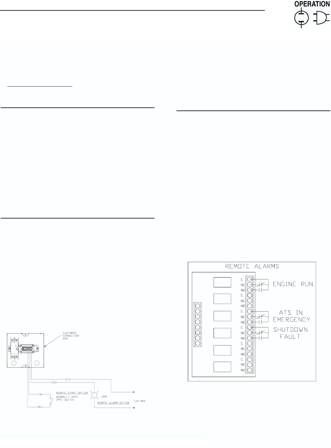
2.6.2 SOUND ATTENUATED UNITS
Model 00844 of the sound attenuated air-cooled
Guardians offers additional features that are not factory
preset (see Figure 2.6):
1. Remote Start – This allows for remote starting of the
generator by means of the #183 and #178 lines with
the Auto/Off/Manual switch set to AUTO.
2. Engine Run Signal – The engine run signal is con-
trolled by the #14 line. The “volt free” engine run
signal relay closes when the #14 line is “hot.”
3. Automatic Transfer Switch (ATS) in Emergency –
For this to be active, a microswitch on the transfer
switch sends a signal along the #231 line to close
the “volt free” contact relay.
4. Shutdown Fault – This signal is controlled by the
main printed circuit board along the #229 line.
When a common fault occurs (low oil pressure,
high temperature, overspeed, overcrank), the
control board will send a signal along the #229
line to close the "volt free" contact relay.
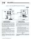
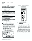
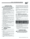
Figure 2.6 – Remote Alarms
◆
◆
◆
Section 2 — Operation
Guardian Air-cooled Generators
Generac
®
Power Systems, Inc. 21