


Generac
®
Power Systems, Inc. 19
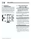
2.3 SEQUENCE OF
AUTOMATIC OPERATION
The generator’s control panel houses a control logic
circuit board. This board constantly monitors utili-
ty power source voltage. Should that voltage drop
below a preset level, circuit board action will signal
the engine to crank and start. After the engine
starts, the circuit board signals the transfer switch
to activate and connect load circuits to the standby
power supply (load terminal lugs T1/T2 connect to
terminal lugs E1/E2).
Upon restoration of utility source voltage above a
preset level, generator circuit board action signals
the transfer switch to transfer loads back to that
power supply. After retransfer, the engine is signalled
to shut down.
The actual sequence of operation is controlled by
sensors and timers on a control logic circuit board,
as follows:
A.Utility Voltage Dropout Sensor
• This sensor monitors utility source voltage.
• If utility source voltage drops below about 60 per-
cent of the nominal supply voltage, the sensor
energizes a 15-second (SA = six-second) timer.
• Once the timer has expired, the engine will crank
and start.
B.Engine Warm-up Time Delay
• This mechanism lets the engine warm up for
about 10 (SA = 15) seconds before the load is
transferred to a standby source.
C.Standby Voltage Sensor
• This sensor monitors generator AC output volt-
age. When the voltage has reached 50 percent of
the nominal rated voltage, transfer to standby
can occur.
D.Utility Voltage Pickup Sensor
• This sensor monitors utility power supply volt-
age. When that voltage is restored above 80 per-
cent of the nominal source voltage, a retransfer
time delay starts timing.
E.Retransfer Time Delay
• This timer runs for about 15 (SA = six) seconds.
• At end of a 15-second (SA = six-second) delay,
circuit board action de-energizes transfer relay in
the transfer switch.
• Retransfer to utility power source then occurs.
F. Engine Cool-down Timer
• When the load is transferred back to utility power
source, the engine cool-down timer starts timing.
• The timer will run for about one minute, and the
generator will then shut down.
NOTE:
Sound attenuated units have a control module
assembly (CMA) board that reads frequency sig-
nals from the stator battery charge windings and
relates them to engine speed or rpm. When AC fre-
quency reaches about 30 Hertz, cranking is termi-
nated and an engine warmup timer goes ON, run-
ning for approximately 15 seconds.
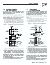
2.4 MANUAL TRANSFER OPERATION
2.4.1 TRANSFER TO GENERATOR
POWER SOURCE
To start the generator and activate the transfer switch
manually, proceed as follows:
1. Set the generator’s Auto/Off/Manual switch to
OFF.
2. Set the generator’s main circuit breaker to its
OFF (or open) position.
3. Turn OFF the utility power supply to the transfer
switch using the means provided (such as a
utility main line circuit breaker).
Do not attempt to activate the transfer switch
manually until all power voltage supplies
to the switch have been positively turned off.
Failure to turn off all power voltage supplies
may result in extremely hazardous and possibly
fatal electrical shock.
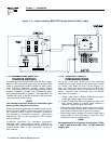
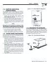
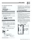
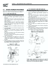
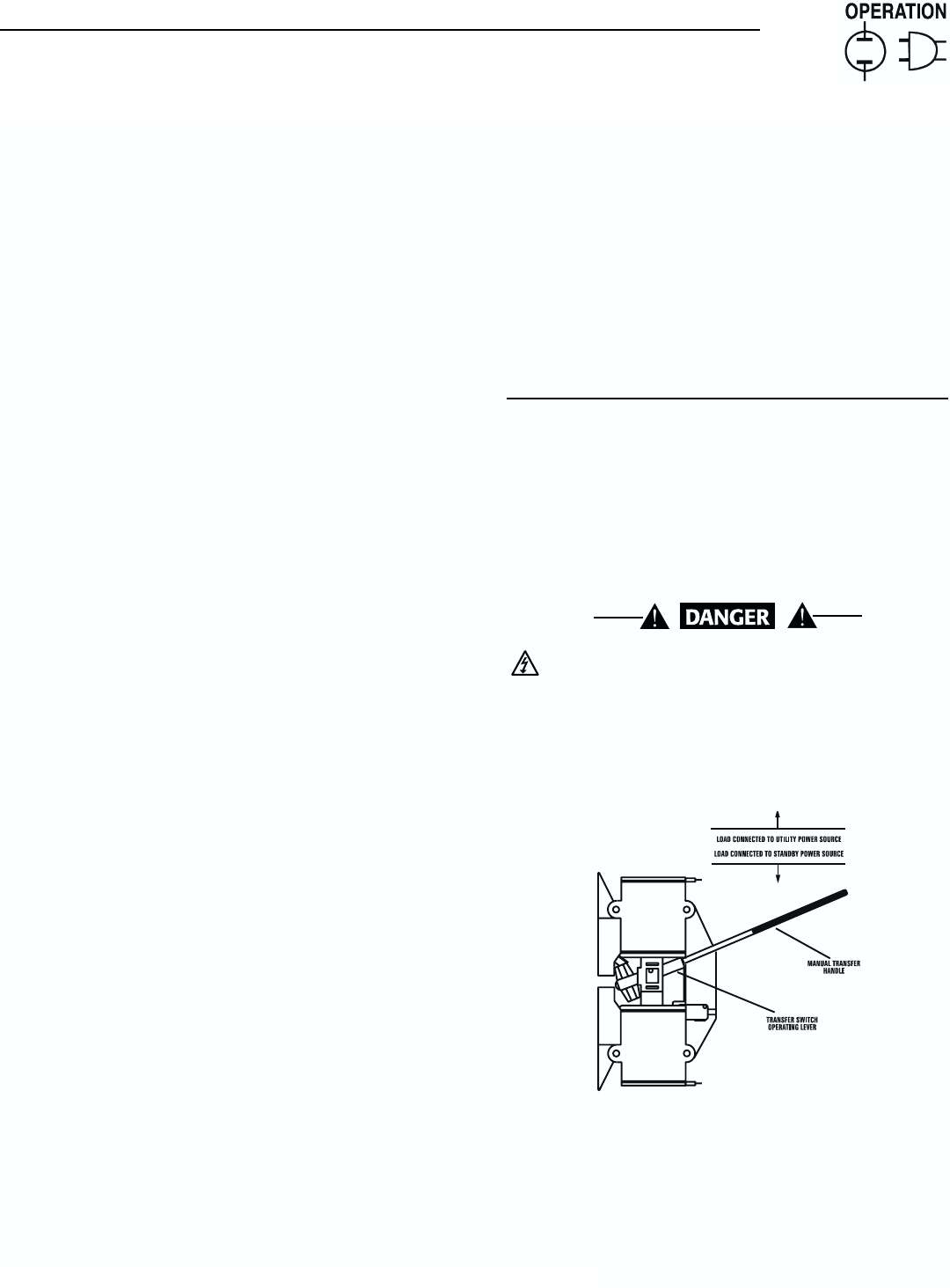
Figure 2.3 – Manual Transfer Switch Operation
4. Use the manual transfer handle inside the trans-
fer switch to move the main contacts to their
“Standby” position, i.e., loads connected to the
standby power source (Figure 2.3).
5. Turn ON the utility power supply to the transfer
switch using the means provided (such as a
utility main line circuit breaker).
◆
Section 2 — Operation
Guardian Air-cooled Generators