


14 Generac
®
Power Systems, Inc.
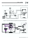
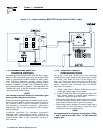
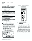
1.12 GENERATORS AND GTS
TRANSFER SWITCHES
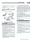
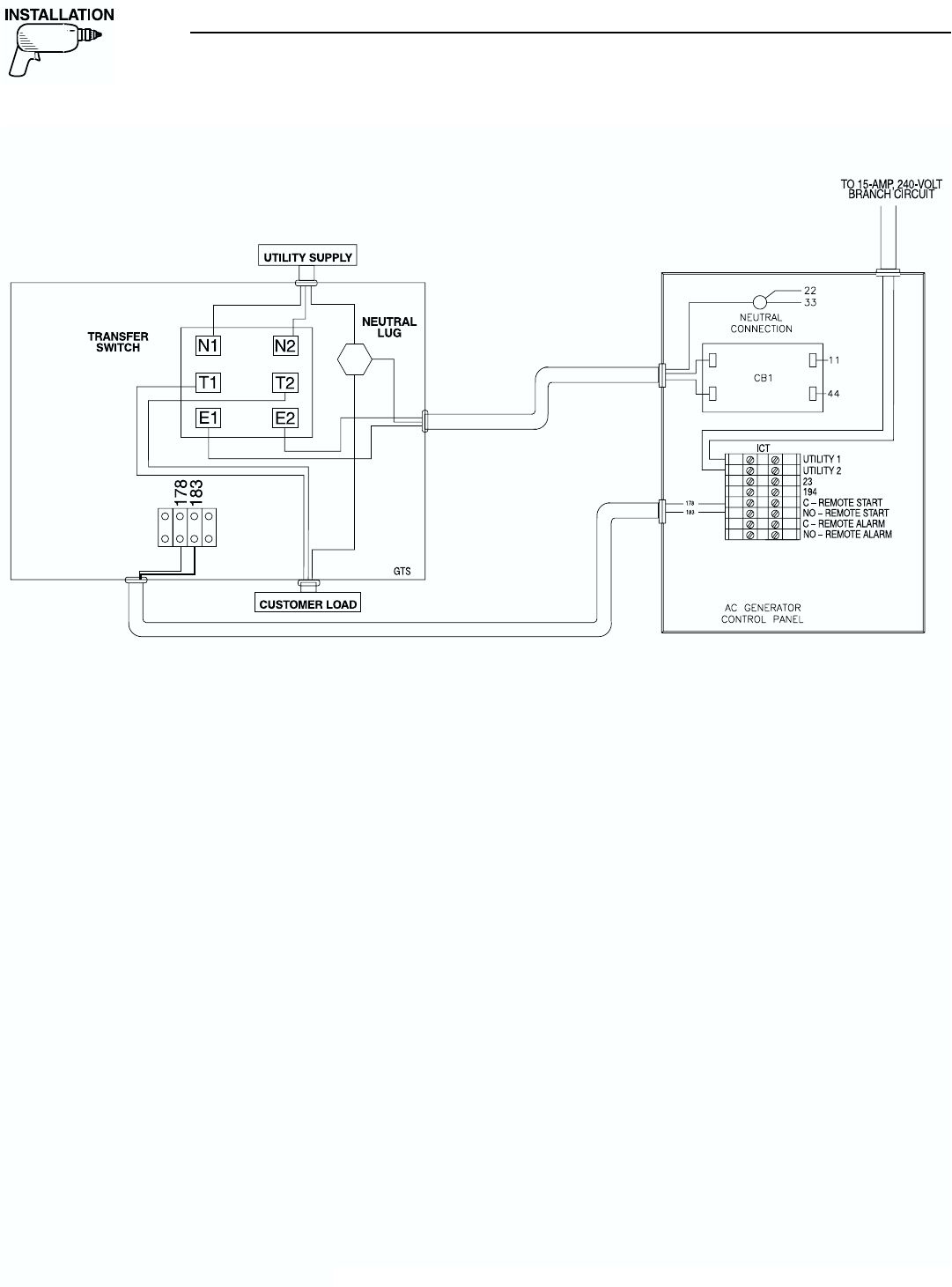
Guardian generators (this DOES NOT APPLY to single-
phase sound attenuated units) may be installed with
either a prepackaged transfer switch or with a stan-
dard GTS-type automatic transfer switch (Figure
1.11). You can do this by connecting generator control
console terminals 178 and 183 to identically num-
bered terminals in the GTS switch. Turn dip switch #2
“Remote Not Auto” to the ON position on the generator
control printed circuit board.
NOTE:
The enclosure roof will need to be removed to gain
access to the printed circuit board.
When a Guardian generator is installed with a stan-
dard GTS-type switch, solid-state circuit boards in
the transfer switch control automatic operation.
For automatic operating sequences, parameters
and timing, refer to the appropriate GTS transfer
switch manual.
Automatic operation for Guardian generators
installed with prepackaged transfer switches is
controlled by a control module circuit board in the
control panel. Refer to the “Operation” section of
this manual.
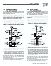
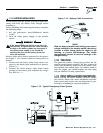
1.13 CONTROL CIRCUIT
INTERCONNECTIONS
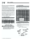
For 6 kw, 8 kW and 10 kW units (not including
sound attenuated), these interconnections consist
of “Utility” and leads 23 and 194 (see Figure 1.9,
Page 13). These four leads must be routed in con-
duit that is separate from the generator AC power
leads. Control lead functions may be briefly
described as follows:
1. Utility 1 and Utility 2: Deliver utility source power
to the generator's logic circuit board.
2. Leads 23 and 194: After the generator starts, the
logic circuit board in control panel delivers a
“transfer” signal via these two leads.
• When logic circuit board action closes this circuit,
it causes transfer switch main contacts to activate
and connect load circuits to generator output.
• When utility source voltage is restored, logic board
opens leads 23 and 194 circuit. Loads are then
transferred back to utility circuit.
NOTE:
Recommended size of control circuit leads (Utility
1 and 2, and 23 and 194) is No. 14 AWG stranded
copper wire.
Section 1 — Installation
Guardian Air-cooled Generators
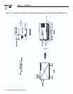
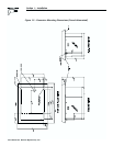
Figure 1.11 – Interconnection With GTS Transfer Switch (100A, y-type)