


5
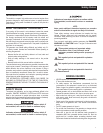
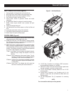
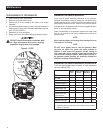
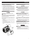
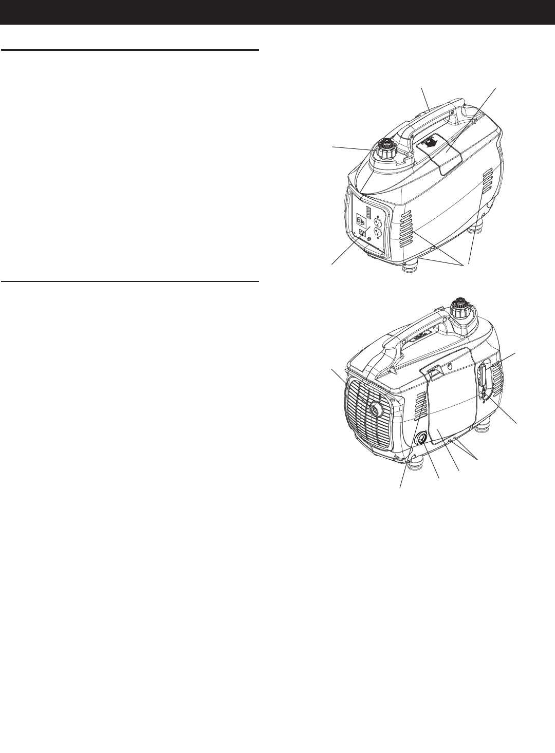
UNIT IDENTIFICATION (Figure 2)
1. Carrying Handle: Lift the generator by this handle only.
2. Spark Plug Cover: Allows access to the engine spark plug.
3. Primer Bulb: Used to prime the fuel system for starting.
4. Fuel Tank Cap: Access to fuel tank for filling.
5. Control Panel: location of generator controls and output
receptacles.
6. Air Intake Slats: Allows for cooling air to enter the housing.
7. Muffler: Lowers engine exhaust noise (includes the spark
arrestor).
8. Choke: Cold engine starting aid
9. Left Side Service Cover: Allows access to air filter, fuel filter and
oil fill.
10. Vent Hoses: Hoses allow venting of the carburetor.
11. Fuel Shutoff: Controls fuel supply to the carburetor.
12. Starter Rope: Pull rope for starting engine.
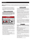
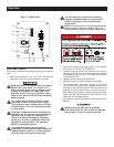
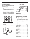
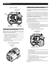
CONTROL PANEL (Figure 3)
13. LOW OIL LEVEL LED (yellow): Lights up when oil level is below
safe operating level and the engine shuts down.
14. OVERLOAD LED (red): This LED indicates a system overload.
This LED should be used in conjunction with the READY LED
which will flash an error code, see No. 15.
15. READY LED (green): Indicates output from the generator unless
there is a low oil or overload condition. In the event of a system
overload the Ready LED will provide an indication of the overload
condition. The indication consists of a series of flashes separated
by a pause. These indications are as follows:
1 Flash = Low Voltage. The unit has been overloaded to the point
where the output voltage has dropped to less than
100V AC.
2 Flashes = High Temperature of the Inverter System. The unit
has been overloaded to the point where the internal
temperature of the inverter has exceeded 212° F.
3 Flashes = Overload. The unit has been overloaded to the point
that the output power required has exceeded 110%
of rated power.
4 Flashes = Short Circuit. This indicates the unit's output has
been short circuited by the load connected to it.
Figure 2 - Unit Identification
1
2
3
4
5
6
7
8
9
10
11
12
16. 12 VDC Plug: Connection for re-charging 12VDC automotive-
style batteries while generator is in operation.
17. FlexPower™ Switch: This switch slows the engine speed when
the load is reduced to save fuel and engine wear.
18. 12 VDC Circuit Breaker: Overload protection for the 12 VDC
charging system.
19. Ground (Earth) Connection Lug: Grounding point for the
generator; consult state and local electrical codes before use
(floating ground).
20. 120 VAC Receptacles: Two (2) receptacles for connecting
devices.
NOTE:
Do not exceed the rated output of the generator.
General Information