


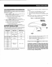

Groups
and
Assembly
Numbers
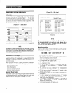
The
XPL
label
lists
the
groups
and
corresponding
assembly
numbers
for
each
unit.
The
assembly
numbers
refer
to
exploded
view
drawing
numbers
that
are
applicable
to
the
specific
gen-
erator
model.
These
drawings
are
located
in
the
back
half
of
this
manual.
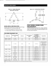
Voltage
Codes
The
identification
code
letter
following
the
unit's
kilowatt
rating
is
the
generator's
"voltage
code."
Anyone
of
the
following
voltage
codes
may
be
listed.
A -
120/240
volts,
single-phase,
four-lead,
60
Hz
o -
120/240
volts,
single-
and
three-phase,
12-lead,
60
Hz
G -
120/208
volts,
three-phase,
12-lead,
60
Hz
Broad
Range
J
120/240
volts,
three-phase,
12-lead,
60
Hz
Broad
Range
K -
277/480
volts,
three-phase,
12-lead,
60
Hz
Broad
Range
L
346/600
volts,
three-phase,
six-lead,
60
Hz
M -
110/220
volts,
single-phase,
four-lead,
50
Hz
N -
115/200
volts,
three-phase,
12-lead,
50
Hz
Broad
Range
P -
100/200
volts,
three-phase,
12-lead,
50
Hz
Broad
Range
R -
231/400
volts,
three-phase,
12-lead,
50
Hz
Broad
Range
S
277/480
volts,
three-phase,
six-lead,
50
Hz
EQUIPMENT
DESCRIPTION
This
equipment
is
a
revolving
field,
alternating
current
generator
set.
The
generator
was
designed
to
supply
electrical
power
for
the
operation
of
compatible
electrical
loads-when
the
UTILITY
power
supply
is
not
available
or
has
dropped
to
an
unacceptable
level.
The
generator's
revolving
field
is
directly
connected
to
and
driven
by
an
engine
by
means
of
flexible
discs.
Generators
with
a
four-
pole
rotor
are
driven
at
rated
speeds
of
1,800
rpm
to
supply
a
frequency
of
60
Hertz.
Refer
to
the
data
label
on
this
specific
generator
or
to
the
data
label
affixed
to
the
unit
for
rated
AC
voltage,
wattage,
amperage,
number
of
phases,
etc.
See
"Identification
Code"
for
an
explanation
of
the
way
to
identify
the
unit's
features.
STANDARD
GENERATOR
FEATURES
This
generator
incorporates
the
following
generator
features:
•
The
rotor
insulation
system
is
Class
"H"
rated,
and
the
stator
insulation
is
Class
"H"
rated
as
defined
by
NEMA
MG1-22.4
and
NEMA
MG1-1.65.
•
The
generator
is
self
-ventilated
and
drip-proof
constructed.
•
The
voltage
waveform
deviation,
total
harmonic
content
of
the
AC
waveform
and
"telephone
influence
factor"
have
been
evaluated
and
are
acceptable
according
to
NEMA
MG1-22.
•
All
prototype
tested
models
have
passed
three-phase
sym-
metrical
short
circuit
test
to
ensure
system
protection
and
reliability.
General Information
ENGINE
PROTECTIVE
DEVICES
The
stationary
emergency
generator
may
be
required
to
operate
for
long
periods
of
time
without
an
operator
on
hand
to
monitor
such
engine
conditions
as
coolant
temperature,
oil
pressure
or
rpm.
For
that
reason,
the
engine
has
several
devices
designed
to
protect
it
against
potentially
damaging
conditions
by
automatically
shutting
down
the
unit
when
the
oil
pressure
is
too
low,
the
coolant
temperature
is
too
high,
the
coolant
level
is
too
low,
or
the
engine
is
running
too
fast.
NOTE:
Engine
protective
switches
and
sensors
are
mentioned
here
for
the
reader's
convenience.
Also
refer
to
the
applicable
control
panel
manual
for
additional
automatic
engine
shutdown
infor-
mation.
COOLANT
TEMPERATURE
SENDER
This
sender
automatically
shuts
down
the
engine
if
the
engine
coolant
temperature
rises
above
a
safe
level.
LOW
COOLANT
LEVEL
SENSOR
Should
the
engine
coolant
level
drop
below
the
level
of
the
high
coolant
temperature
switch,
it
is
possible
for
the
engine
to
overheat
without
automatic
shutdown.
To
prevent
such
overheating,
the
engine
has
a
low
coolant
level
sensor.
If
the
level
of
engine
coolant
drops
below
the
level
of
the
low
coolant
level
sensor,
the
engine
automatically
shuts
down.
OIL
PRESSURE
SENDER
This
sender
monitors
oil
pressure
in
the
engine.
If
oil
pressure
drops
below
a
safe
level,
the
control
system
automatically
shuts
down
the
engine.
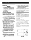
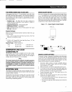
OVERSPEED
SHUTDOWN
A
speed
circuit
controls
engine
cranking,
start-up,
operation
and
shutdown.
Engine
speed
signals
are
delivered
to
the
circuit
board
whenever
the
unit
is
running.
Should
the
engine
overspeed
above
a
safe,
preset
value,
the
circuit
board
initiates
an
automatic
engine
shutdown.
OVERCRANK
SHUTOOWN
After
a
prespecified
duration
of
cranking,
this
function
ends
the
cranking
if
the
engine
has
failed
to
start.
RPM
SENSOR
LOSS
SHUTDOWN
If
the
speed
signal
to
the
control
panel
is
lost,
engine
shutdown
will
occur.
DC
FUSES
These
fuses
are
located
inside
the
front
panel
of
the
control
sys-
tem.
They
protect
the
panel
wiring
and
components
from
damag-
ing
overload.
5