


Operation
Fuel
System
Make
sure
the
fuel
supply
system
to
the
generator
(a)
delivers
the
correct
fuel
at
the
correct
pressure
and
(b)
is
properly
purged
and
leak
tested
according
to
code.
No
fuel
leakage
is
permitted.
See
"Specifications"
for
more
information
If
the
unit
has
been
idle
for
a
long
period
of
time,
or
if
the
fuel
lines
or
system
components
have
been
removed
and
reinstalled,
the
fuel
system
may
require
bleeding
to
remove
air
from
the
system.
Air
in
the
fuel
system
causes
hard
starting
and
rough
operation.
All
fuel
system
lines
must
be
installed
and
must
be
tight A
loose
line
may
show
no
sign
of
leakage,
but
may
draw
air
into
the
system.
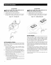
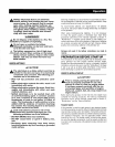
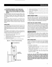
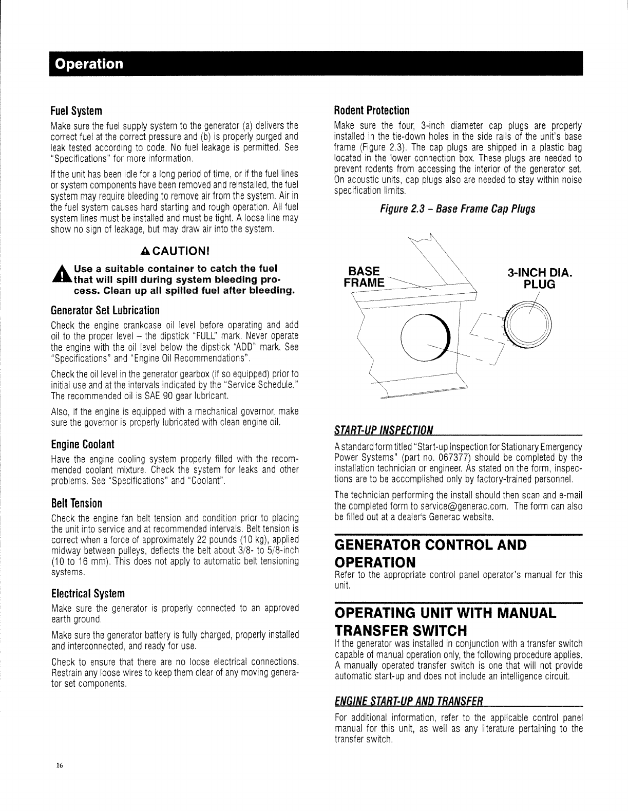
Rodent
Protection
Make
sure
the
four,
3-inch
diameter
cap
plugs
are
properly
installed
in
the
tie-down
holes
in
the
side
rails
of
the
unit's
base
frame
(Figure
2.3).
The
cap
plugs
are
shipped
in
a
plastic
bag
located
in
the
lower
connection
box.
These
plugs
are
needed
to
prevent
rodents
from
accessing
the
interior
of
the
generator
set
On
acoustic
units,
cap
plugs
also
are
needed
to
stay
within
noise
specification
limits.
Figure
2.3
-
Base
Frame
Cap
Plugs
ACAUTIONI
GENERATOR
CONTROL
AND
OPERATION
Refer
to
the
appropriate
control
panel
operator's
manual
for
this
unit
OPERATING
UNIT
WITH
MANUAL
TRANSFER
SWITCH
If
the
generator
was
installed
in
conjunction
with
a
transfer
switch
capable
of
manual
operation
only,
the
following
procedure
applies.
A
manually
operated
transfer
switch
is
one
that
will
not
provide
automatic
start-up
and
does
not
include
an
intelligence
circuit
A
standard
form
titled
"Start-up
Inspection
for
Stationary
Emergency
Power
Systems"
(part
no.
067377)
should
be
completed
by
the
installation
technician
or
engineer.
As
stated
on
the
form,
inspec-
tions
are
to
be
accomplished
only
by
factory-trained
personnel.
The
technician
performing
the
install
should
then
scan
and
e-mail
the
completed
form
to
service@generac.com.
The
form
can
also
be
filled
out
at
a
dealer's
Generac
website.
3-INCH CIA.
PLUG
BASE
FRAME
STA8r-UP
INSPECTION
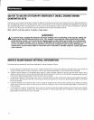
Belt
Tension
Check
the
engine
fan
belt
tension
and
condition
prior
to
placing
the
unit
into
service
and
at
recommended
intervals.
Belt
tension
is
correct
when
a
force
of
approximately
22
pounds
(10
kg),
applied
midway
between
pulleys,
deflects
the
belt
about
3/8-
to
5/8-inch
(10
to
16
mm).
This
does
not
apply
to
automatic
belt
tensioning
systems.
Electrical
System
Make
sure
the
generator
is
properly
connected
to
an
approved
earth
ground.
Make
sure
the
generator
battery
is
fUlly
charged,
properly
installed
and
interconnected,
and
ready
for
use.
Check
to
ensure
that
there
are
no
loose
electrical
connections,
Restrain
any
loose
wires
to
keep
them
clear
of
any
moving
genera-
tor
set
components.
Engine
Coolant
Have
the
engine
cooling
system
properly
filled
with
the
recom-
mended
coolant
mixture.
Check
the
system
for
leaks
and
other
problems.
See
"Specifications"
and
"Coolant"
A Use a suitable container to catch the fuel
....
that will spill during system bleeding pro-
cess. Clean up all spilled fuel after bleeding.
Generator
Set
Lubrication
Check
the
engine
crankcase
oil
level
befol'e
operating
and add
oil
to
the
proper
level
-
the
dipstick
"FULL'
mark.
Never
operate
the
engine
with
the
oil
level
below
the
dipstick
"ADD"
mark.
See
"Specifications"
and
"Engine
Oil
Recommendations"
Check
the
oil
level
in
the
generator
gearbox
(if
so
equipped)
prior
to
initial
use
and
at
the
intervals
indicated
by
the"
Service
Schedule."
The
recommended
oil
is
SAE
90
gear
lubricant
Also,
if
the
engine
is
equipped
with
a
mechanical
governor,
make
sure
the
governor
is
properly
lubricated
with
clean
engine
oil.
ENGINE
STA8T-UP
AND
TRANSFE8
For
additional
information,
refer
to
the
applicable
control
panel
manual
for
this
unit,
as
well
as
any
literature
pertaining
to
the
transfer
switch.
16