


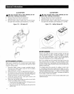
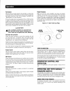

Lubed
58
Ft-Lbs
Lubed
65
Ft-Lbs
-------_.
__
_--_
..
_-------
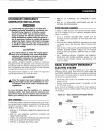
FIELD
WIRING
CONNECTIONS
TO
BUSS
BARS
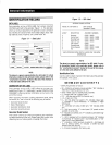
Units
supplied
with
Series
C- R
Frame
Breakers
rated
1600,
2000
and
2500A
have
Buss
Bars
suppled
in
the
connection
Module
for
the
connection
of
the
Field
Conductors.
The
following
information
should
be
followed
in
order
to
obtain
a
suitable
electrical
connec-
tion
to
the
Buss
Bars.
•
Conductor
lugs
-
The
Buss
Bars
have
been
configured
to
accept
Aluminum
Compression
Lugs
suitable
for
copper
or
aluminum
stranded
wire.
•
Suggested
Manufacturer
-
PENN
UNION
CORP
•
Manufacturers
Part
No.
-
BLUA060D2
•
Type
-
Dual
Rated
(AL/CU),
Two
1/2"
Studs
spaced
1
3/4"
Apart
•
Wire
Size
-
600
kcmil
Required
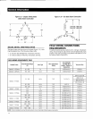
Hardware
Below
is
the
recommended
hardware
required
to
attach
the
Lugs
to
the
Buss
Bars.
•
M12
x
65mm
Grade
8.8
Hex
Head
Cap
Screw,
M12
Flat
Washers,
Lock
Washer
and
Nut
or
•
1/2"-20
x
2.5"
Grade
SAE
5
Hex
Head
Cap
Screw,
1/2"
Flat
Washers,
Lock
Washer
and
Nut
Required
Torque
-
Tighten
fasteners
to:
M12
Dry
75
Ft-Lbs
1/2"
Dry
85
Ft-Lbs
GENERATOR
AND
LOAD
COMPATIBILITY
The
generator
must
be
fully
compatible
with
the
rated
voltage,
phase
and
frequency
of
the
connected
electrical
loads.
The
gen-
erator,
connected
electrical
devices,
or
both,
can
be
damaged
if
voltage,
phase
and
frequency
are
not
compatible.
NOTE:
This
manual
assumes
that
the
stationary
emergency
generator
has
been
properly
selected,
installed
and
interconnected
by
a
competent,
qualified
electrician
or
installation
contractor.
Once
the
installation
is
complete,
do
nothing
that
may
result
in
non-
compatibility
between
the
generator
and
connected
electrical
loads.
STARTING
AIDS
The
stationary
emergency
generator
may
be
equipped
with
one
or
more
starting
aids
that
serve
to
provide
quicker,
easier
starts
under
varying
climactic
conditions.
This
generator
may
have
been
mounted
with
(a)
an
engine
coolant
heater,
(b)
an
engine
oil
heater,
(c)
a
battery
warmer
or
(d)
a
bat-
tery
charger.
These
aids
are
powered
by
a
normal
(utility)
power
source
during
nonoperating
periods.
General
Information
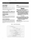
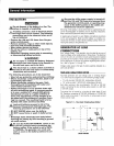
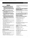
ENGINE
COOLANT
HEATERS
If
the
unit
is
equipped
with
an
engine
coolant
(block)
heater
(Figure
1.11),
it
is
powered
by
a
circuit
normally
fed
by
the
utility
power
supply.
This
heats
the
engine
coolant
when
the
unit
is
not
operat-
ing.
This
action
keeps
the
engine
warm
even
in
cold
weather,
helping
to
ensure
quicker
starts.
Heated
coolant
in
the
engine
rises
continuously
drawing
cold
coolant
into
the
heater,
creating
a
constant
flow
of
warm
coolant
through
the
engine.
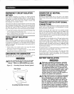
Figure
1.11-
Typical
Engine
Coolanl
Healers
OUTLET
TYPE
A
1~'_KE
__
~
TYPEB
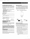
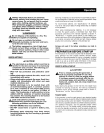
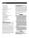
ENGINE
OIL
HEATER
(OPTIONALl
The
engine
oil
heater
is
designed
for
installations
where
the
engine
oil
must
be
kept
near
operating
temperature
at
all
times.
If
included
with
this
unit,
a
low-watt
density
heater
and
thermostat
are
mount-
ed
in
the
engine's
oil
sump
or
on
the
sump
pan
(Figure
1.12).
The
heater
and
thermostat
do
not
require
maintenance.
1.
Disconnect
battery
cables
to
prevent
accidental
start-up.
Disconnect
the
negative
battery
cable
first
from
the
battery
post
indicated
by
(-)
or
NEG.
2.
Make
sure
power
is
off
from
the
appropriate
power
source.
3.
To
connect
the
wires,
hold
the
bare
metal
leads
together
and
place
a
wire
nut
over
them,
then
twist
clockwise
until
tight.
For
all
these
connections,
use
the
wire
nuts
provided.
4.
Connect
the
ground
wire
from
120V
power
source
to
the
ground
wire
from
oil
heater.
5.
Using
wire
nuts
provided
connect
the
white
wire
and
black
wire
from
the
oil
heater
as
follows:
•
The
white
(common)
power
wire
from
120V
power
source
to
1
st
wire
from
the
oil
heater.
•
The
wire
from
load
side
of
thermostat
to
2nd
wire
from
the
oil
heater.
11