


Installation
EMERGENCY
CIRCUIT
ISOLATION
METHOD
This
prevents
overloading
the
generator
by
keeping
electrical
loads
below
the
wattage/amperage
capacity
of
the
generator,
If
the
generator
is
powering
only
critical
loads,
within
the
wattage/
amperage
capacity,
during
utility
power
outages,
consider
using
the
emergency
circuit
isolation
method,
Critical
electrical
loads
are
grouped
together
and
wired
into
a
sepa-
rate
"Emergency
Distribution
Panel."
Load
circuits
powered
by
that
panel
are
within
the
wattage/amperage
capacity
of
the
generator
set.
When
this
method
is
used,
it
is
difficult
to
overload
the
gen-
erator,
The
transfer
switch
must
meet
the
requirements:
•
It
must
have
an
ampere
rating
equal
to
the
total
amperage
rating
of
the
emergency
distribution
panel
circuit.
•
Have
it
installed
between
the
building's
main
distribution
panel
and
the
emergency
distribution
panel.
TOTAL
CIRCUIT
ISOLATION
METHOD
When
a
generator
capable
of
powering
all
electrical
loads
in
the
circuit
is
to
be
installed,
use
the
"Total
Circuit
Isolation
Method,"
It
is
possible
for
the
generator
to
be
overloaded
when
this
isolation
method
is
employed,
The
following
apply
to
the
transfer
switch
in
this
type
of
system,
•
Ampere
rating
of
the
transfer
switch
must
the
ampere
rating
of
the
normal
incoming
utility
service,
•
The
transfer
switch
is
installed
between
the
utility
service
entrance
and
the
building
distribution
panel.
GROUNDING
THE
GENERATOR
The
generator
set
must
be
grounded
in
accordance
with
the
National
Electrical
Code
and
any
state
or
local
requirements,
~
A Do not connect the ground wire to any pipe
~that
carries a flammable or explosive sub-
stance - FIRE or an EXPLOSION may result.
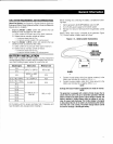
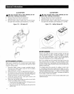
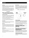
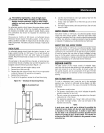
Figure
2.2 -
Grounding
Electrode
Terminal
(typical)
Base
Frame
Grounding
Electrode
Terminal
14
GENERATOR
AC
NEUTRAL
CONNECTIONS
Grounding
is
recommended
only
at
one
point
in
the
system,
Consult
local
building
codes
for
proper
neutral
grounding
require-
ments,
TRANSFER
SWITCH
START
SIGNAL
CONNECTIONS
If
the
generator
is
to
be
installed
with
a
standard
automatic
transfer
switch,
such
as
a
GTS
type
switch,
it
will
be
necessary
to
connect
the
two-wire
start
control
system,
Connect
the
two-wire
start
signal
from
the
automatic
transfer
switch
to
the
automatic
start
connection,
which
is
located
in
the
lower
rear
of
the
AC
connection
panel.
Match
wires
178
(0)
and
183
In
the
transfer
SWitch
to
178
(0)
and
183
on
the
terminal
strip
In
the
connection
box,
The
conductors
for
the
two-wire
start
circuit
must
be
in
their
own
conduit.
If
the
generator
is
to
be
installed
with
an
HTS-type
transfer
switch
a
different
connection
method
is
needed,
Use
shielded
2-wir~
communications
cable
(such
a
Belden
#9460)
to
make
the
con-
nection
from
the
HTS
transfer
switch
to
the
engine
generator
connection
panel.
This
cable
is
to
be
routed
in
a
separate
conduit
between
the
HTS
transfer
switch
and
the
generator,
The
cable
is
to
be
connected
as
follows:
HTS
transfer
switch
- 4
position
terminal
block,
in
the
bottom
of
the
transfer
switch
enclosure
(labeled
"comm,
Ports"),
Engine
generator
-
terminal
strip
located
in
the
lower
rear
of
the
AC
connection
panel.
Connect
the
RS485+
and
RS485-
to
the
respective
terminals
in
switch
and
generator.
Do
not
connect
the
shield
at
the
transfer
switch
end.
BATTERY
INSTALLATION
~
A Stationary emergency generators installed
....
with automatic transfer switches will crank
and start
automatically when NORMAL (UTIL-
ITY)
source voltage is removed or is below
an
acceptable preset level.
To
prevent such
automatic start-up and possible injury to per-
sonnel, do not connect battery cables until
certain that normal source voltage at the
transfer switch is
correct and the system Is
ready
to be placed Into operation.
A Storage batteries give off explosive hydrogen
~gas.
This gas can form an explosive mixture
around the battery for several hours after
charging. The slightest spark
can ignite the
gas and cause an explosion. Such an explo-
sion
can shatter the battery and cause blind-
ness
or
other injury. Any area that houses a
storage battery must
be
properly ventilated.
Do not allow smoking, open flame, sparks or
any spark producing tools or equipment near
the battery.