General Information
ACAUTIONI
A.
Be
sure
no
bare wire or wire strands are vis-
~Ible
after making connections.
6.
Push
all
wires
and
wire
nuts
into
junction
box.
7.
Assemble
junction
box
cover
to
junction
box
8.
Reconnect
battery
cables
to
battery
posts.
Connect
the
posi-
tive
cable
first
to
the
battery
post
indicated
by
(+)
or
POS.
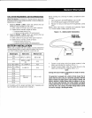
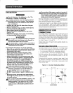
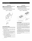
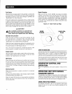
Figure
1.12
-
Oil
Heater
Kit
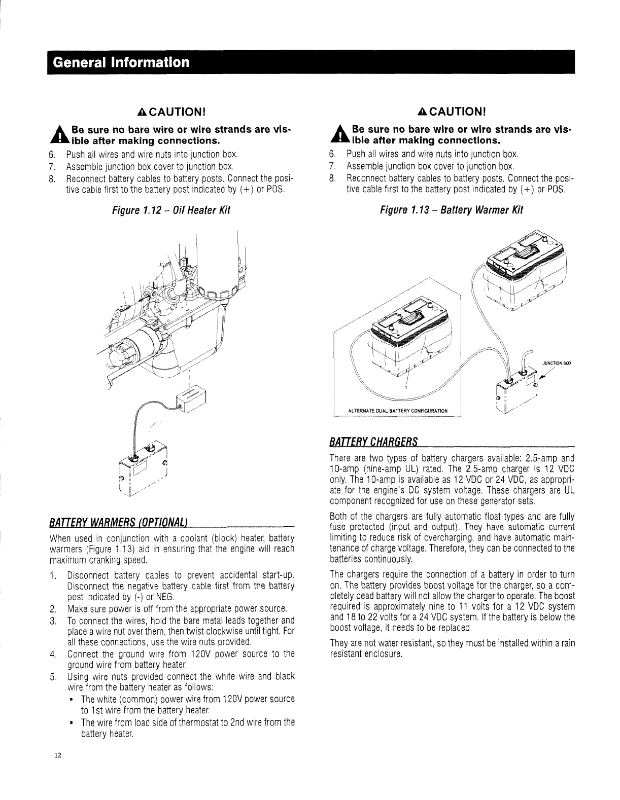
BATTERY
WARMERS
(OPTIONAL)
When
used
in
conjunction
with
a
coolant
(block)
heater,
battery
warmers
(Figure
1.13)
aid
in
ensuring
that
the
engine
will
reach
maximum
cranking
speed.
1,
Disconnect
battery
cables
to
prevent
accidental
start-up.
Disconnect
the
negative
battery
cable
first
from
the
battery
post
indicated
by
(-)
or
NEG,
2.
Make
sure
power
is
off
from
the
appropriate
power
source,
3,
To
connect
the
wires,
hold
the
bare
metal
leads
together
and
place
a
wire
nut
over
them,
then
twist
clockwise
until
tight.
For
all
these
connections,
use
the
wire
nuts
provided.
4,
Connect
the
ground
wire
from
120V
power
source
to
the
ground
wire
from
battery
heater.
5,
Using
wire
nuts
provided
connect
the
white
wire
and
black
wire
from
the
battery
heater
as
follows:
•
The
white
(common)
power
wire
from
120V
power
source
to
1
st
wire
from
the
battery
heater,
•
The
wire
from
load
side
of
thermostat
to
2nd
wire
from
the
battery
heater,
12
ACAUTIONI
A.
Be
sure
no
bare wire or wire strands are vis-
~
Ible after making connections.
6.
Push
all
wires
and
wire
nuts
into
junction
box,
7.
Assemble
junction
box
cover
to
junction
box,
8,
Reconnect
battery
cables
to
battery
posts,
Connect
the
posi-
tive
cable
first
to
the
battery
post
indicated
by
(+)
or
POS,
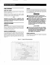
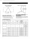
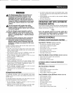
Figure
1.13
-
Battery
Warmer
Kit
BATTERY
CHARGERS
There
are
two
types
of
battery
chargers
available:
2,5-amp
and
10-amp
(nine-amp
UL)
rated,
The
2,5-amp
charger
is
12
VDC
only.
The
1
Q-amp
is
available
as
12
VDC
or
24
VDC,
as
appropri-
ate
for
the
engine's
DC
system
voltage,
These
chargers
are
UL
component
recognized
for
use
on
these
generator
sets.
Both
of
the
chargers
are
fully
automatic
float
types
and
are
fully
fuse
protected
(input
and
output),
They
have
automatic
current
limiting
to
reduce
risk
of
overcharging,
and
have
automatic
main-
tenance
of
charge
voltage.
Therefore,
they
can
be
connected
to
the
batteries
continuously,
The
chargers
require
the
connection
of
a
battery
in
order
to
turn
on,
The
battery
provides
boost
voltage
for
the
charger,
so
a
com-
pletely
dead
battery
will
not
allow
the
charger
to
operate.
The
boost
required
is
approximately
nine
to
11
volts
for
a
12
VDC
system
and
18
to
22
volts
for
a
24
VDC
system,
If
the
battery
is
below
the
boost
voltage,
it
needs
to
be
replaced.
They
are
not
water
resistant,
so
they
must
be
installed
within
a
rain
resistant
enclosure.


