


You set the limits with the following
commands in the calculate subsystem.
:CALCulate:LIMit:UPPer and
:CALCulate:LIMit:LOWer
An example on how to use limit monitor
-
ing is available in Chapter 4, ‘Program
Examples.’
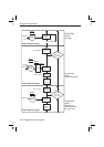
Bit Definition
Bit 2 (weight 4) — Monitor of Low Limit
This bit is set when the low limit is
passed from above.
Bit 1 (weight 2) — Monitor of High Limit
This bit is set when the high limit is
passed from below.
n
Summary, Device-defined
Status Reporting
:STAT:DREG0:ENAB <bit mask>
Enable reporting of device-defined status
in the status byte.
*SRE 1
Enable SRQ when a limit is exceeded.
:STAT:DREG0?
Reading and clearing the event register of
Device Register structure 0.
–
If bit 1 is true, the high limit has been ex
-
ceeded.
–
If bit 2 is true, the low limit has been ex
-
ceeded.
Power-on Status Clear
Power-on clears all event enable regis
-
ters and the service request enable regis
-
ter if the power-on status clear flag is set
TRUE (see the common command
*PSC.)
n
Preset the Status Reporting
Structure
You can preset the complete status struc-
ture to a known state with a single com-
mand, the STATus:PRESet command,
which does the following:
–
Disables all bits in the Standard Event
Register, the Operation Status Register, and
the Questionable Data Register
–
Enables all bits in Device Register 0
–
Leaves the Service Request Enable Regis
-
ter unaffected.
6-26 Status Subsystem
Using the Subsystems
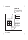
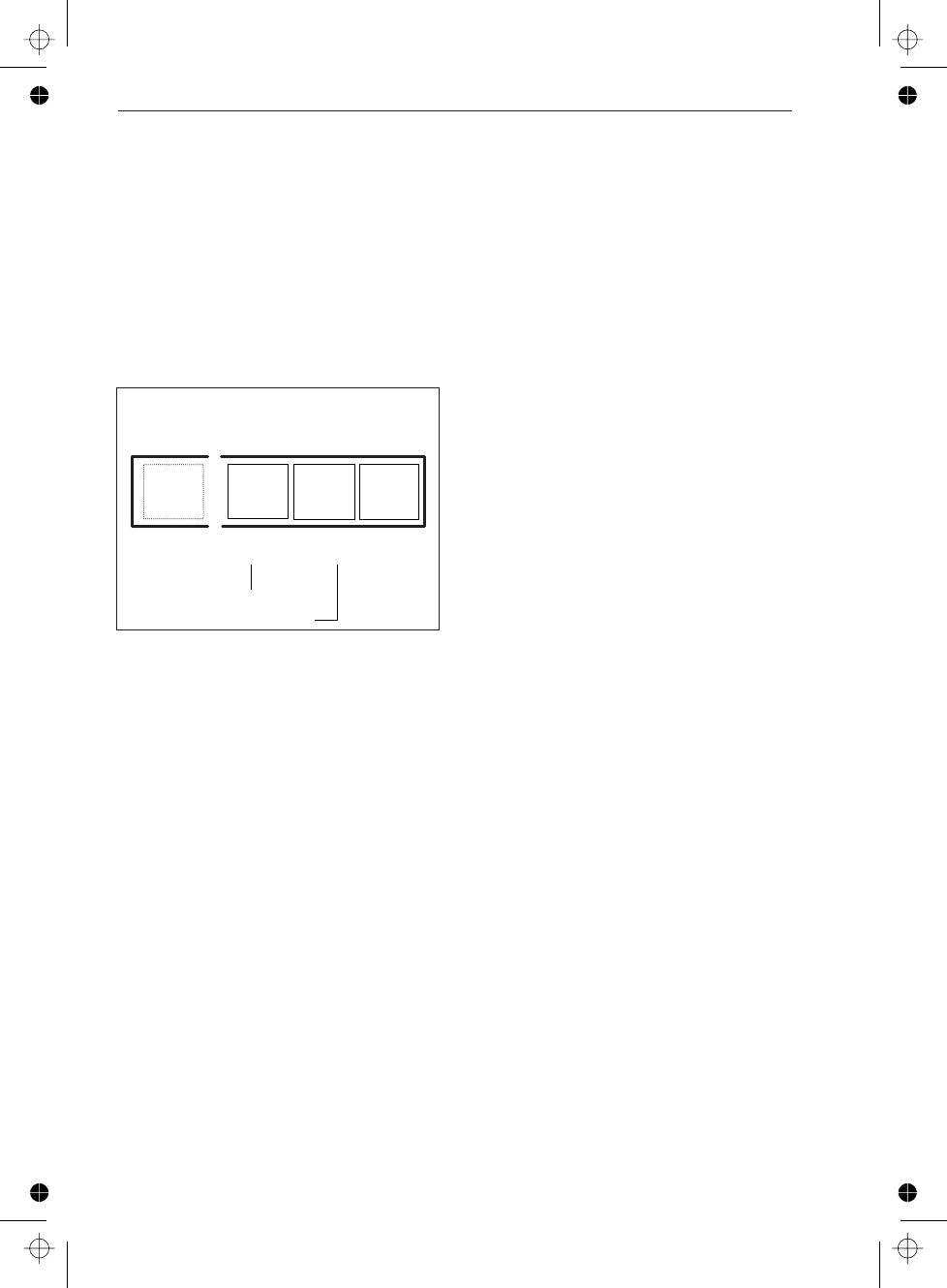
24
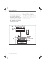
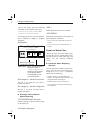
Monitoring of high limit
Monitorin
g
of low limit
Device Status Register0
STAT:DREG0:COND?
STAT:DREG0?
21015
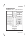
Figure 6-14 Bits in the Device Status
Register number 0.
:STATus:DREGister0?
Reads out the contents
of the Device Status
event Register 0 and
clears the register.