


The area around the calibrator must be kept clear to allow adequate ventilation.
The air is directed from the bottom to the top and may be hot. Allow 6 inches
of open space around the calibrator to allow adequate ventilation.
Fuse Holders - On the rear panel are four user accessible fuse holders.
WARNING: Always leave enough clearance to allow for safe and easy
installation and removal of probes.
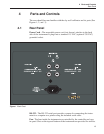
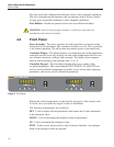
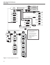
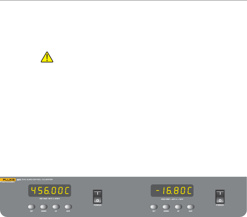
4.2 Front Panel
Power Switches - The power switches for both controllers are located on the
front panel of the instrument. The switches are either on or off. The on position
is for normal operation. The off position disconnects power to the entire unit.
Controller Display - The digital display is an important part of the temperature
controller because it not only displays set and actual temperatures but also vari
-
ous calibrator functions, settings, and constants. The display shows tempera-
tures in units according to the selected scale °C or °F.
Controller Keypad - The four button keypad allows easy setting of the
set-point temperature. The control buttons (SET, DOWN, UP, and EXIT) are
used to set the calibrator temperature set-point, access and set other operating
parameters, and access and set calibration parameters.
Setting the control temperature is done directly in degrees of the current scale.
It can be set to one-tenth of a degree Celsius or Fahrenheit.
The functions of the buttons are as follows:
SET - Used to display the next parameter in the menu and to store parameters
to the displayed value.
DOWN - Used to decrement the displayed value of parameters.
UP - Used to increment the displayed value.
EXIT - Used to exit a function and to skip to the next function. Any changes
made to the displayed value are ignored.
9011 Dual-Well Calibrator
User’s Guide
14
Figure 2 Front Panel