


20
GAS CONNECTIONS
The heater requires a gas supply of not less than 4” wc and
not more than 14” wc. Gas supply pressures outside of this
range may result in improper burner operation. A minimum
inlet pressure of 4” wc is required to maintain input rating.
The gas supply must be installed in accordance with the
National Fuel Gas Code, ANSI Z223.1, and all applicable
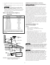
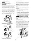
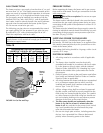
local codes. Install a manual shut-off valve and a sediment
trap and union located outside the heater jacket (Figure
22). Do not use a restrictive gas cock.
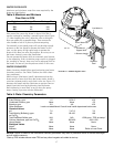
The following gas pipe sizes are recommended for natural
gas supply piping. For low pressure LP gas, pipe size may
be reduced by 1/4”, with a minimum pipe size of 3/4”.
Check for compliance with local codes.
NOTICE: DO NOT use a corrugated flexible gas line to
supply heater. It will not deliver enough gas (at nominal
diameter) to supply heater.
PRESSURE TESTING
Before operating the heater, the heater and its gas connec-
tions must be leak tested. Test all gas connections for leaks
with soapy water.
Risk of fire or explosion. Do not use an open
flame to test for leaks.
The heater and its individual shutoff valve must be discon-
nected from the gas supply piping system during any pres-
sure testing of that system at test pressures in excess of 1/2
psig (3.5 kPa).
The heater must be isolated from the gas supply system by
closing its individual manual shutoff valve during any pres-
sure testing of the gas supply at test pressures equal to or
less than 1/2 psig (3.5 kPa).
SUPPLYING POWER TO THE HEATER
The heater requires a 120V/60Hz/1Ph power supply.
Enclose the 120 Volt line to the heater in an approved flex-
ible conduit connected directly to the junction box on the
inside of the heater jacket.
Line voltage field wiring should be 14 gauge, with a circuit
capacity of 15 amps.
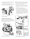
ELECTRICAL WIRING
1. All wiring must be in accordance with all applicable
codes.
2. The heater, when installed, must be electrically
grounded and bonded in accordance with local codes
or, in the absence of local codes, with the National
Electrical Code, ANSI/NFPA 70. A bonding lug is pro-
vided on the outside of the jacket under the vent for
this purpose.
3. Electrical power circuits to the pool heater must follow
local codes and National Electrical Code or Canadian
Electrical Code (as applicable).
4. All wiring between the heater and devices not attached
to it, or between separate devices which are field
installed and located, shall conform to the specifica-
tions of Type T wire (35°C rise).
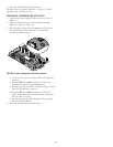
5. All line voltage wiring shall be enclosed in approved
flexible conduit, and shall be securely attached to the
field wiring box located inside the jacket. The conduit
or cable connector at the field wiring box should con-
tain an insulating bushing or its equivalent to prevent
abrasion of the wires as they enter the box.
6. The filter pump should run continuously when the
heater is on, and for at least 15 minutes after the
heater is off. Any switches in the pump circuit (includ-
ing circuit breakers) that can disconnect the pump
must also disconnect the heater.
7. Do not wire single pole switches, including protective
devices, into a grounded line. Observe hot/neutral
polarity when connecting power to the heater.
Manual
Shut-off
Valve
Sediment
Trap
Union
At least 4"
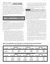
Recommended Pipe Size For Natural Gas
1,000 BTU/ft
3
, 0.6 Sp Gr, 0.5” wc Pressure Drop
Model 0-25’ 26-50’ 51-100’ 101-200’ 201-300’
200 3/4” 1” 1” 1-1/4” 1-1/4”
333 1” 1-1/4” 1-1/4” 1-1/2” 1-1/2”
400 1” 1-1/4” 1-1/4” 1-1/2” 2”
FIGURE 22: Gas line and Trap
Table 10