


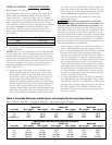
A manual bypass valve should be installed across the
heater when the pump flow exceeds 120 GPM. See
instructions below for setting of the manual bypass.
Make sure that the outlet plumbing from the heater con-
tains no shut-off valves or other flow restrictions that could
prevent flow through the heater (except as noted below).
To switch flow between the pool and spa, use a diverter
valve. Do not use any valve that can shut off the flow.
Do not use a shut-off valve to isolate the heater unless it is
below the level of the pool or spa.
Install a check valve if there is a possibility of back-siphon-
ing through the heater when the pump is off.
NOTICE: Improper operation of chemical feeders can cause
severe damage to the heater which is not covered by the
warranty. Either equip chemical feeders with an anti-siphon
device to prevent chemicals from siphoning into the heater
if the pump shuts off, or install the chemical feeder down-
stream of the heater (see “Water Chemistry,” Page 17).
NOTICE: If the heater is plumbed in backwards, it will
cycle continuously. Make sure piping from filter is not
reversed when installing heater.
WATER PIPING
Connect the heater directly to 2” PVC pipe, using the inte-
gral unions provided. Heat sinks are not required. The low
thermal mass of the heater will prevent overheating of the
piping connected to the heater even if the pump shuts
down unexpectedly.
16
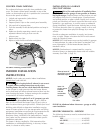
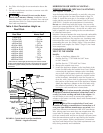
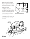
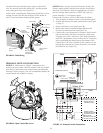
Cool Water
In From Spa
2735 1296
From Filter Outlet
to Heater
Inlet
Warm Water
Out to Pool or Spa
Sanitizer
Corrosion Resistant,
Positive Seal
Check Valve
To Filter
Inlet
Cool Water
In From Pool
To Spa
To Pool
SYSTEM 3
™
Modular Media
Filter
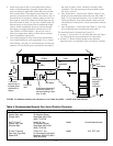
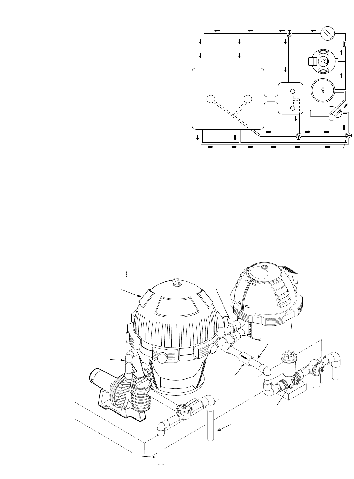
FIGURE 15:
Typical installation
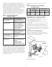
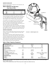
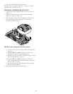
Pool
Main
Drain
Spa
From Pool
3-Way
Valve
3-Way
Valve
3-Way
Valve
Chlorinator
Heater
Filter
Pump
FIGURE 16: Typical pool piping layout