


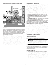
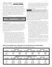
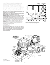
VERTICAL VENTING - NEGATIVE PRESSURE
(See Figures 11 and 12)
Vent the heater vertically in a negative pressure (positive
draft) system in accordance with the National Fuel Gas
Code, ANSI Z223.1, and local codes. Type “B” Double-
wall vent connector is recommended; however single-wall
pipe is allowed by the National Fuel Gas Code in some
circumstances. Consult your local code official for detailed
information. Do not use a draft hood with this heater.
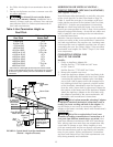
To connect a negative pressure metal gas vent to the
heater, order the appropriate Metal Flue Collar from the
chart below:
1. See Table 3, below, to determine allowable vent sizes
for your heater.
NOTICE: Table 3 is for installations in which the total later-
al vent length (that is, the horizontal distance from the flue
collar to the main vertical portion of the vent) is less than
1/2 the total vent height (the vertical distance from the flue
collar to the vent termination) and which have three or less
elbows in the system. For venting systems which do not
meet these conditions, consult the National Fuel Gas
Code, ANSI Z223.1
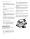
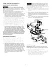
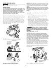
2. Install the metal Flue Collar in the Vent Body of the
heater (located under the outside vent cover). Fasten
the metal Flue Collar to the Vent Body with two #10
sheet metal screws. Use UltraCopper
®
silicone RTV to
seal the metal Flue Collar to the Vent Body. Follow
instructions supplied with the metal Flue Collar. Before
connecting the metal Flue Collar to the Vent Body, wet
a clean cloth or paper towel with isopropyl alcohol
(rubbing alcohol) and vigorously wipe the socket of the
Vent Body. Immediately wipe the cleaned surfaces dry
with a clean cloth or paper towel. Repeat for the exte-
rior of the 4” end of the metal Flue Collar. Attach the
metal Flue Collar to the Vent Body using the RTV sup-
plied with the kit, following the instructions included
with kit. Do not use a draft hood with this heater.
3. Attach the vent pipe to the metal Flue Collar with
sheet-metal screws.
Risk of fire or asphyxiation if vent is not
assembled according to manufacturer’s instructions or if
vent parts from different manufacturers are mixed. Vent
parts from different manufacturers ARE NOT interchange-
able. Mixing parts from more than one manufacturer may
cause leaks or damage to vent. When assembling a vent,
pick one manufacturer and be sure that all vent parts come
from that manufacturer and are specified by the manufac-
turer for your system. Follow manufacturer’s instructions
and local and National Fuel Gas Code requirements care-
fully during assembly and installation.
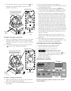
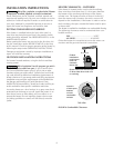
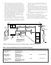
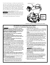
4. Install vent pipe so that it can expand and contract
freely as the temperature changes. Support the vent
pipe according to applicable codes and the vent manu-
facturer’s instructions. Pipe support must allow the
vent pipe free movement out and back, from side to
side, or up and down as necessary, without putting a
strain on the heater or vent body. Slope horizontal pipe
runs up from the heater at least 1/4” per foot. Install
Listed condensate drains at low points where conden-
sate might collect. Plumb condensate drains to a drain
through hard piping or high-temperature tubing such
as silicone rubber or EPDM rubber – do not use vinyl
or other low temperature tubing. Follow drain manu-
facturer’s installation instructions.
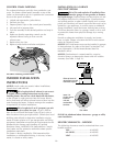
5. Use Listed firestops for floor and ceiling penetrations.
Use Listed thimble for wall penetrations. Use a Listed
roof flashing, roof jack, or roof thimble for all roof pen-
etrations. Do not fill the space around the vent (that is,
the clear air space in the thimble or firestop) with
insulation. The roof opening must be located so that
the vent is vertical.
12
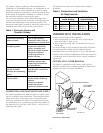
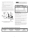
Table 3: Permitted Minimum and Maximum Vent Heights By Size and Heater Model
Read “VERTICAL VENTING – NEGATIVE PRESSURE” (above) before using this table.
Type B Double Wall Vent With Type B Double Wall Connector
Model 200 Model 333 Model 400
Vent Size Min. Height Max. Height Min. Height Max. Height Min. Height Max. Height
6 in. 6 Ft. 100 Ft. 30 Ft. 100 Ft. Not Rec. Not Rec.
7 in. 6 Ft. 100 Ft. 10 Ft. 100 Ft. 15 Ft. 100 Ft.
8 in. 6 Ft. 100 Ft. 6 Ft. 100 Ft. 8 Ft. 100 Ft.
9 and 10 in. 6 Ft. 50 Ft. 6 Ft. 100 Ft. 6 Ft. 100 Ft.
Type B Double Wall Vent With Single Wall Connector
Model 200 Model 333 Model 400
Vent Size Min. Height Max. Height Min. Height Max. Height Min. Height Max. Height
6 in. 6 Ft. 15 Ft. Not Rec. Not Rec. Not Rec. Not Rec.
7 in. 6 Ft. 8 Ft. 10 Ft. 20 Ft. 15 Ft. 50 Ft.
8 in. Not Rec. Not Rec. 6 Ft. 20 Ft. 8 Ft. 20 Ft.
9 in. Not Rec. Not Rec. Not Rec. Not Rec. 6 Ft. 6 Ft.
10 in. Not Rec. Not Rec. Not Rec. Not Rec. Not Rec. Not Rec.
Metal Flue Collar Sta-Rite Part No.
4x6” 77707-0076
4x8” 77707-0077