


19
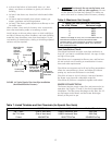
To avoid water damage or scalding from operation of the
relief valve, install a drain pipe in the outlet of the pressure
relief valve that will direct water discharging from the
valve to a safe place for disposal. Do not install any reduc-
ing couplings or valves in the drain pipe. The drain pipe
must be installed so as to allow complete drainage from
the valve and drain line. The relief valve should be tested
at least once a year by lifting the valve lever.
Explosion hazard. Any heater installed with
restrictive devices in the piping system downstream from
the heater (including check valves, isolation valves, flow
nozzles, or therapeutic pool valving) must have a relief
valve installed as described above. See Page 16.
Risk of fire and explosion. Improper
installation, adjustment, alteration, service, or main-
tenance of the Combination Gas Control Valve can
lead to fire or explosion, causing loss of life, per-
sonal injury, or property damage.
These instructions are for the use of qualified
service technicians only!
Do not attempt this procedure unless you have
been trained and certified in the care and repair of
gas-fired appliances!
Do not attempt this procedure if the following
instructions are confusing!
This appliance is equipped with an unconventional gas
control valve that is factory set with a manifold pressure
of –.2” wc. Installation or service must be performed by
a qualified installer, service agency, or the gas supplier.
If this control valve is replaced, it must be replaced with
an identical control.
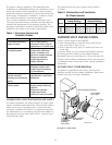
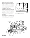
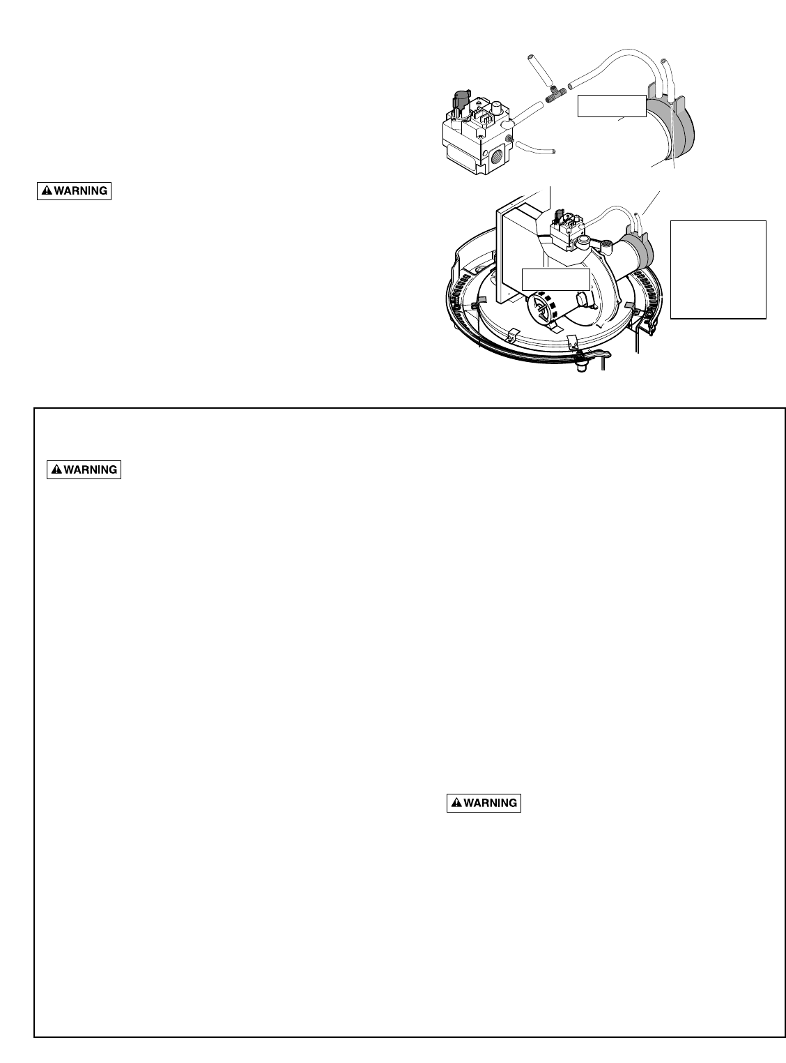
The combination gas valve incorporates dual shut-off
valves and a negative-pressure regulator. For proper
operation, the regulated pressure at the outlet manifold
of the valve must be 0.2” wc below the reference pres-
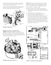
sure at the blower mixer inlet, and the gas valve ‘VENT’
tap must be connected to the endcap air orifice as
shown in Figure 21 (above).
Do not attempt to adjust the gas input by adjusting the
regulator setting. The correct gas regulator setting is
required to maintain proper combustion and must not be
altered.
To check that the gas pressure setting is correct,
use the following procedure:
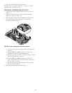
1. Turn off the heater and remove the top covers for
access to the Combination Gas Control Valve.
2. Use a 3/16” hex key to remove the plug from the
‘PRESSURE TAP’ port on the outlet side of the
Combination Gas Control Valve.
3. Install a 1/8” NPT barbed fitting into the ‘PRESSURE
TAP’ port. Use a flexible tube to connect it to the low
side of a differential pressure gauge or a slope
gauge.
NOTICE: If you are using a slope gauge or a differ-
ential pressure gauge of less than 3” capacity, close
the shutoff valve of the gauge to avoid pulling the liq-
uid out of the gauge when the blower starts.
4. Disconnect the tube from the Gas Valve ‘VENT’ port.
Connect it to a tube with a tee running to the high
side of a differential pressure gauge and to the blow-
er’s air orifice grille (See Figure 21, above).
5. Turn on the heater and verify the gas supply pres-
sure (Page 20).
6. After the burner ignites, open the shutoff valve of the
gauge. The pressure gauge should then read 0.2” wc
±0.1” wc (0.0” to 0.1” wc = rich mixture; 0.3” to 0.5”
wc = lean mixture). (Since the pressure tap is con-
nected to the low side of the gauge, the pressure is
actually negative.)
Risk of fire or explosion if
Combination Gas Control Valve is incorrectly
adjusted. If it is necessary to adjust the gas
valve, this must be done only by a qualified
service agency.
7. Turn off the heater.
8. Replace the plastic hose between the ‘VENT’ port
and the inlet of blower mixer. Remove the barbed fit-
ting and replace the plug in the ‘PRESSURE TAP’
port of the gas valve, using a thread sealant
approved for use with natural gas and LPG.
9. Replace the heater covers and cycle the heater to
check for proper operation.
Instructions For Checking the Gas Pressure
Through the Combination Gas Control Valve
PRESS
TAP
VENT
PILOT
OFF
OFF
ON
ON
CAUTION
2788 0397
P
RE
S
S
T
A
B
VE
N
T
P
IL
OT
O
F
F
OFF
O
N
ON
Connection for
Service
Connection for
Test
To Air Flow
Switch
To High Side of Differential
Pressure Gauge
To Low Side of Diff.
Pressure Gauge
NOTICE: The gas
piping and unions
are not shown
for clarity; make
this test with all
gas piping
connected (as for
normal service).
FIGURE 21: Connect Gas Valve to End Cap Air Orifice