


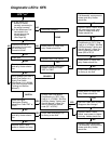


36
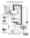
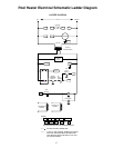
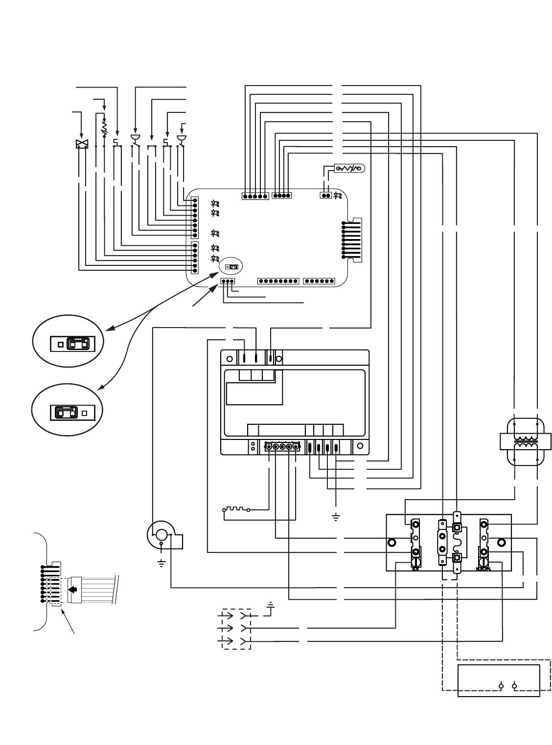
Pool Heater Wiring Connection Diagram
JMP3
9
1
J6
JMP3
1
JMP3
1
External Control Interface Circuit
Disabled, Heater Membrane Pad
Enabled
External Control Interface
Circuit Enabled, "Pool On"
and "Spa On" Keys Disabled.
"OFF" Key on Membrane
Pad Remains Functional.
CONNECTION DIAGRAM
AGS Switch
Stack Flue Sensor
Gas Valve
Air Flow Switch
Extra Switch 1
Hi-Limit Switch
Pressure Switch
VAL
TH
IND
GND
24VAC
24VAC
FS
THERMISTOR
OPERATING CONTROL
1
PS
HLS
ES1
AFS
AGS
SFS
GAS
CONTROL CENTER
SPA CONTROL
VERSION 1 PAD
MEMBRANE PAD
CONNECTION
Spa Line
Common Line
Pool Line
IGNITION CONTROL
MODULE
DIAGNOSTIC INDICATOR
F1 F2
24
VAC
FC1
FC2
S1/
120
L1
L1
L2
BM
FL
F1
L2
S2
TH IND
VAL GND
GND
GND
GND
BLOWER
120VAC
120VAC (HOT)
120VAC
IGNITER
MOT
TRANS
TRANS
GROUND (GND)
NEUTRAL (NEU)
JUNCTION BOX
F
I
R
E
M
A
N
S
S
W
I
T
C
H
Replace jumper with leads to
Fireman's Switch (field installed)
24VAC
SEC
PRIM
120VAC
Y/W
Y/W
Y/R
Y/O
Y/BL
BK
GY GY
BK
BK
W
W
BK
W
W
WW
G
G
Y
Y
YY
BK
BK
Y/W
W
W
R
R
BL
BL
O
O
O
O
PR
PR
Y/R
Y/BL
Y/O
Y/W
Y
Y
Y
Y
Y
YY Y Y
BR
BR
3661 0200
External Control Interface
If cable from Membrane Pad
is a 6-Conductor Cable, connect
it to pins 4 - 9 on Operating
Control Board as shown.
Y
9
1
J6
NOTICE: If, while there is 120VAC connected to the heater, you touch
either 120VAC terminal with any 24VAC wire that is connected to the
control board (including the Fireman's Switch jumper), you will
immediately destroy the control board and void the warranty.