


DESCRIPTION OF THE HEATER
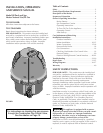
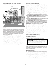
FIGURE 2
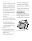
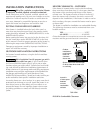
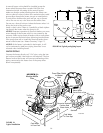
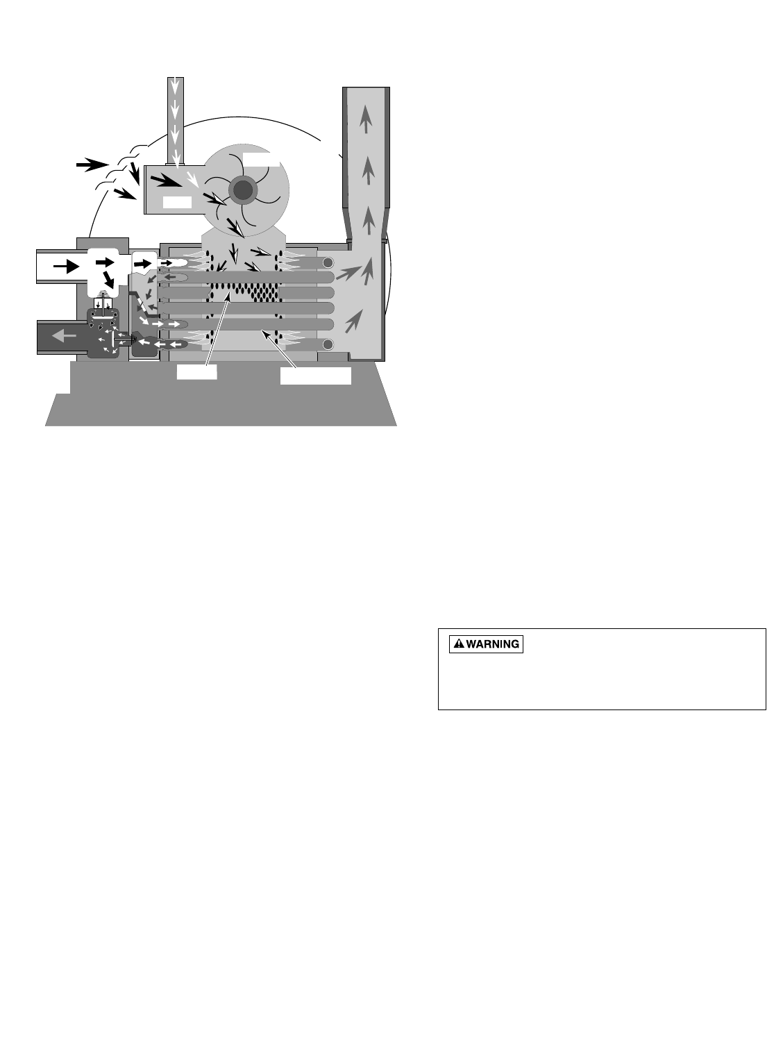
Figure 2 is a diagram of the heater showing how it operates.
Precisely matched orifice plates meter the air and gas into
the mixer. The blower draws the air and gas through the
mixer and forces it into the burner’s flameholder. A sealed
heat exchanger surrounds the flameholder, discharging
exhaust gases out the flue.
Two inch PVC water piping connects directly to the mani-
fold/header on the heat exchanger using 2” PVC slip unions
provided with the heater. The outer manifold remains cool;
no heat sinks are required. A thermal regulator and an inter-
nal bypass regulate the water flow through the heat
exchanger to maintain the correct outlet temperature.
A plastic jacket with the top half split for access surrounds
the assembly. The heater control board assembly, set into
the top of the jacket, contains the operating controls.
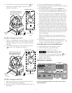
SEQUENCE OF OPERATION
An electronic temperature sensing thermistor in the mani-
fold adapter inlet controls the heater operation. When the
inlet water temperature drops below the temperature set on
the operating control, the burner controller supplies
power to the combustion air blower through a series of
safety interlocks. The interlocks consist of
• the pressure switch (PS), which senses that the pump is
running,
• the high limit switch (HLS), which opens if the heat
exchanger outlet temperature goes above 135°F, and
• the automatic gas shutoff (AGS) switch, which opens if
the heat exchanger outlet temperature goes above
140°F.
• the stack flue sensor (SFS), which shuts down the heater
if the flue gas temperature reaches 500°F.
The air flow switch (AFS) senses the pressure drop across
the air metering orifice. As soon as there is sufficient air
flow, the AFS closes, closing the circuit to the hot surface
ignition (HSI), which ignites the fuel mixture.
On a call for heat, the blower and HSI are energized. In
about 20 seconds, the gas valve opens and ignition occurs.
The HSI then switches to a sensing mode and monitors the
flame.
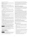
The heater is equipped with a digital operating control that
enables the user to pre-set the desired pool and spa water
temperatures. The control enables the user to select
between pool and spa heating, and features a digital dis-
play that indicates the water temperature.
OWNER’S OPERATING
INSTRUCTIONS
FOR YOUR SAFETY READ BEFORE OPERATING
IF YOU DO NOT FOLLOW THESE
INSTRUCTIONS EXACTLY, A FIRE OR EXPLOSION
MAY RESULT, CAUSING PROPERTY DAMAGE,
PERSONAL INJURY OR LOSS OF LIFE.
START-UP AND OPERATION
START-UP AND SHUTDOWN INSTRUCTIONS ARE ON
THE LABEL ATTACHED TO THE COVER OF THE APPLI-
ANCE CONTROL BOX.
BEFORE START-UP
A. This appliance does not have a pilot. It is equipped
with an ignition device which automatically lights the
burner. Do not try to light the burner by hand.
B. BEFORE OPERATING check for odor. Sniff all around
the appliance area for gas. Be sure to sniff next to the
floor, because some gas (such as propane) is heavier
than air and will settle on the floor.
4
Gas
Air
Mixer
Blower
Inlet
(Cold
Water)
Exhaust
Heating Coils
Outlet
(Mixed
Water)
Burner