


• at least 4 feet below or horizontally from, or 1 foot
above, any doors or windows or gravity air inlet to a
building
• At least 3 feet above any forced air inlet located within
10 feet
• At least 4 feet horizontally from electric meters, gas
meters, regulators and relief equipment
• At least 7 feet above grade adjacent to walkways or sim-
ilar traffic areas.
Allow at least 3 feet vertical clearance over vent termina-
tion when terminating under an overhang or deck.
Avoid corners or alcoves where snow or wind could have
an effect. Exhaust may affect shrubbery and some building
materials. Keep shrubbery away from termination. To pre-
vent staining or deterioration, sealing or shielding exposed
surfaces may be required.
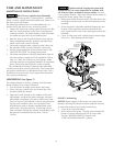
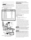
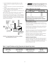
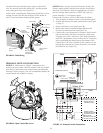
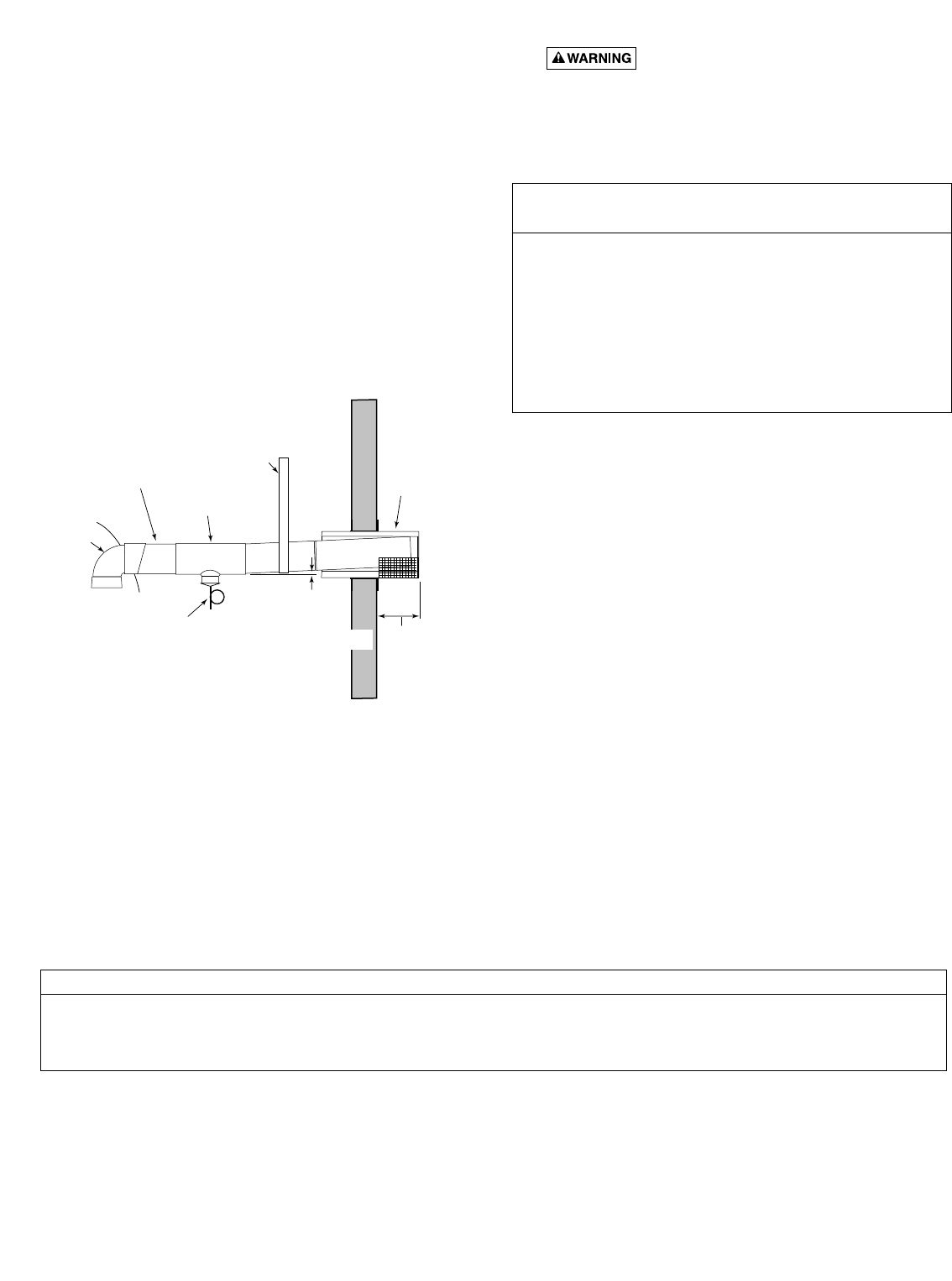
FIGURE 14: Typical Special Gas Vent Pipe Installation
(Horizontal-Positive Pressure)
8. Fire Hazard. Do not run the heater vent
into a common vent with any other appliance. Do not
run the Special Gas Vent into, through, or within any
active vent such as a factory built or masonry chimney.
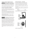
Table 6: Maximum Vent Length
Final Installation Check:
Check that horizontal vent pipe runs slope uniformly at
least 1/4” per foot to condensate drain(s). No sags, no dips,
no high or low spots.
Check that vent is supported at elbows, tees, and horizon-
tal and vertical runs according to manufacturer’s instruc-
tions and code requirements.
Check that vent supports and wall and ceiling penetrations
allow free movements up, down, and sideways without
putting any strains on the heater or vent body.
Check for at least six (6) inch free air clearance between
the heater vent pipe and combustible materials.
Check that all joints are completely together and sealed.
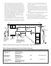
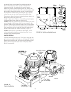
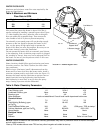
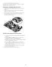
WATER CONNECTIONS
The heater requires proper water flow and pressure for its
operation. See Figures 15 and 16 for the recommended
installation. The filter pump discharges to the filter, the fil-
ter discharges to the heater, and the heater discharges
directly to the pool or spa.
15
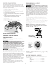
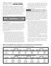
Vent Brand Wall Thimble Horizontal Terminal Vertical Terminal
Saf-T Vent
®
(Part of Vent term.) 5490CI Horizontal Term. 5400 Cap
Saf-T CI Vent
®
(Part of Vent term.) 5490CI Horizontal Term. 5400 Cap
Z-Vent 2SVSWTF04 2SVSTTF04 Tee 2SVSRCF04 Cap
Table 7: Listed Thimbles and Vent Terminals (for Special Gas Vents)
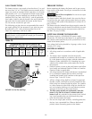
4” Special Gas Vent (Vertical or Horizontal)*
No. of 90° Elbows Maximum Length
0 50 Ft.
2 40 Ft.
4 30 Ft.
6 20 Ft.
* Minimum vent length is one (1) foot, or in accordance with vent
manufacturer’s instructions, and local and national codes.
Horizontal vents 3’ or less in length do not require a condensate
tee, but must slope down toward the outlet at 1/4” to the foot to
allow condensate to drain.
Condensate
drain w/Trap
Condensate
Tee
2787 0297
Slope at least
1/4" per foot
down towards
condensate drain
Support
weight
of pipe
Listed
Terminal
3" Minimum,
12" Maximum
Clearance
Metal Special
Gas Vent
requires
Appliance
Adapter
Metal
Vent
Body