


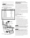
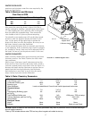
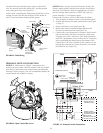
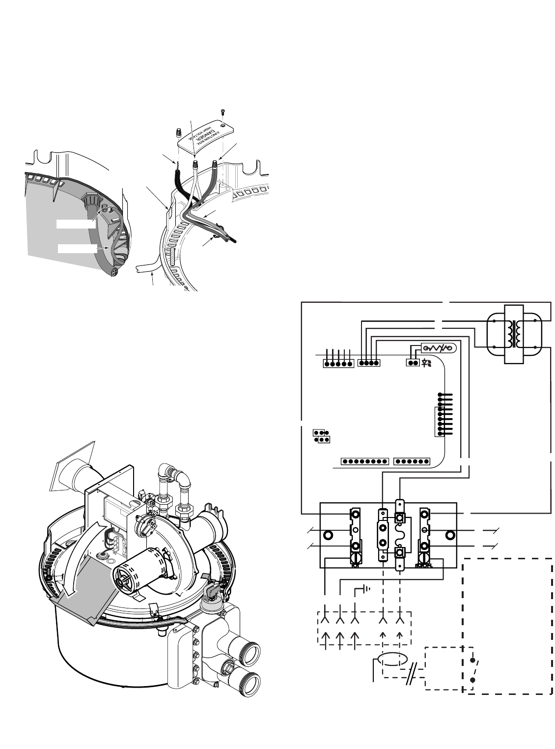
Connect the hot lead of the power supply to the black
wire, the neutral lead to the white wire, and the ground
wire to the green wire (See Figure 23).
A time clock controlling the filter pump should have a low-
voltage Fireman’s Switch that switches off the heater at
least 15 minutes before shutting off the pump.
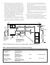
FIREMAN’S SWITCH CONNECTION
NOTICE: If, while there is 120VAC connected to the
heater, you touch either 120VAC terminal with any 24VAC
wire that is connected to the control board (including the
Fireman’s Switch jumper), you will immediately destroy the
control board and void the warranty.
NOTICE: When using a timer and Fireman’s Switch, the
heater’s power supply should come from the load side of
the timer. The Fireman’s Switch completes the circuit for
the low voltage safety switches. It DOES NOT get any
power from the 115 volt power supply.
Connect the Fireman’s switch to the heater as follows:
1. Turn off power to heater at main circuit breaker panel.
2. Unbolt and remove the upper jacket halves (see Figure
3, Page 5).
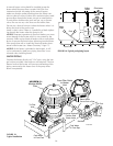
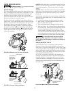
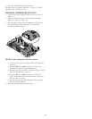
3. Open control box cover (see Figure 24).
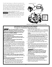
4. Remove the factory-installed jumper between the
Fireman’s Switch terminals (see Figure 25).
5. Connect the wires between the Fireman’s Switch termi-
nals on the heater and those on the time clock using
18 gauge wire with a minimum 3/64” thick insulation
rated for a temperature rise of at least 105°C. Route the
wires out through the knockout on the bottom of the
Control Box. Use a 90° conduit el and conduit run out
through the cutout on the Lower Enclosure, next to the
Junction Box (see Figure 23).
21
Wire into bottom
of Junction-box
in Flexible Conduit
Wiring Harness
to Control Box
Black to
Black
White to White
Green (Ground)
to
Green (Ground)
Bonding Wire
Bonding
Wire
Bonding Lug
View From Below
(Exterior)
View From Above
(Interior)
Cutout for
Conduit from
Fireman's Switch
P
R
E
S
S
T
A
B
V
E
N
T
P
IL
O
T
OF
F
OFF
O
N
ON
GND
120VAC (HOT)
GROUND (GND)
NEUTRAL (NEU)
JUNCTION BOX
L1
L2
BM
FL
F1
TRANS
TRANS
F
I
R
E
M
A
N
S
S
W
I
T
C
H
Fireman's Switch
Completes the heater
24 Volt AC Control
Board Circuit.
DO NOT connect this
circuit to 115 Volt AC!
24VAC
SEC
PRIM
120VAC
YY
BK
BK
BK
W
W
W
W
W
G
Y
Y
JMP3
VAL
TH
IND
GND
24VAC
24VAC
FS
THERMISTOR
OPERATING CONTROL
DISABLE TOGGLE
ENABLE TOGGLE
1
CONTROL CENTER
SPA CONTROL
VERSION 1 PAD
MEMBRANE PAD
CONNECTION
TERMINAL BOARD
TRANS
TRANS
TRANS
TRANS
FUSE
FUSE
NEUTRAL
Time Clock or Remote
(Purchase Separately –
Supplies Power to
Circulator Pump)
3663 0200
24VAC
FIGURE 24: Open Control Box Cover
FIGURE 25: Fireman’s Switch Connections
FIGURE 23: Field Wiring