


Maintenance
because of the jumper wire being used. Run
engine at full throttle and release brake.
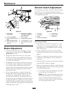
7. The reverse indicator spring must be correct
before the following adjustments can be made.
See the Reverse Indicator Adjustment section.
Note: The motion control lever needs to be in
neutral while making any necessary adjustments.
The left rod assembly controls the left wheel and
the right rod assembly controls the right wheel.
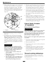
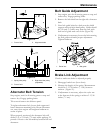
8. Bring the motion control lever into the neutral
position. Adjust RH pump control rod length
by rotating the double nuts on the rod in the
appropriate direction until the wheels slightly
creep in reverse (
Figure 27). Move the motion
control lever to the reverse position and while
applying slight pressure to the lever allow the
reverse indicator spring to bring the levers back to
neutral. The wheel must stop turning or slightly
creep in reverse. When adjustment is complete,
tighten lock nuts onto ball joints.
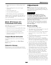
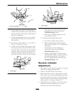
9. Bring the LH motion control lever into the
neutral position. Adjust the LH pump control rod
length by rotating the tracking adjustment knob in
the appropriate direction until the wheels slightly
creep in reverse. Move the motion control lever
to the reverse position and while applying slight
pressure to the lever allow the reverse indicator
spring to bring the levers back to neutral. The
wheel must stop turning or slightly creep in
reverse (
Figure 28).
Figure 28
Left-Hand Side of Unit
1. Turn LH tracking adjustment knob. (Do Not loosen any
nuts on LH side)
10. Shut off unit. Remove jumper wire from wire
harness connector and plug connector into seat
switch.
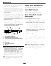
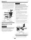
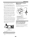
Motion Control Damper
Adjustment
The top damper mounting bolt can be adjusted to
obtain a more desired motion control lever resistance.
See
Figure 29 for mounting options.
Figure 29
1. Motion control bracket
2. Least resistance (softest feel)
3. Medium resistance (medium feel)
4. Most resistance (rmest feel)
5. Torque nyloc nut to 200 in-lb (16.7 ft-lb). Bolt must
protrude past end of nyloc nut after torque.
6. Damper
7. Damper must move freely on bolt.
Caster Pivot Bearings
Pre-Load Adjustment
Remove dust cap from caster and tighten nyloc nut
until washers are at and back off 1/4 of a turn
to properly set the pre-load on the bearings. If
disassembled, make sure the spring disc washers are
reinstalled as shown in
Figure 30.
45