


Maintenance
• Square head setscrews on Hydro pump control
arms.
• Sheave retaining bolt in the end of engine
crankshaft.
• Caster wheel spacer nuts.
• Fuel tank bulkhead tting nuts.
• Bolts retaining stub shaft to engine ywheel.
Adhesives such as “Loctite RC/609 or RC/680” or
“Fel-Pro Pro-Lock Retaining I or Retaining II” are
used on the following:
Fuel tank studs, where studs are inserted into tank.
Mobil HTS Grease (Or
Food-Grade Anti-seize)
Mobil HTS grease (or food-grade anti-seize) is used
in the following locations:
• Between the cutter housing spindle and bearings.
• Between the cutter housing spindle and sheave.
• Under top cutter housing bearing guard.
• Between the jackshaft and bearings and the
jackshaft and sheaves.
Copper-Based Anti-seize
Copper-based anti-seize is used in the following
location:
On threads of Blade Bolts. See Check Mower
Blades section.
Dielectric Grease
Dielectric grease is used on all blade type electrical
connections to prevent corrosion and loss of contact.
Adjustments
Note: Disengage PTO, shut off engine, wait for
all moving parts to stop, engage parking brake, and
remove key before servicing, cleaning, or making any
adjustments to the unit.
CAUTION
Raising the mower deck for service or
maintenance relying solely on mechanical
or hydraulic jacks could be dangerous. The
mechanical or hydraulic jacks may not be enough
support or may malfunction allowing the unit to
fall, which could cause injury.
Do Not rely solely on mechanical or hydraulic
jacks for support. Use adequate jack stands or
equivalent support.
Deck Leveling
1. Position mower on a at surface.
2. Stop engine, wait for all moving parts to stop, and
remove key. Engage parking brake.
3. Check tire pressure in drive tires. Proper ination
pressure for tires is 10 psi (69 kPa). Adjust if
necessary.
4. Set anti-scalp rollers to top holes or remove them
completely for this adjustment.
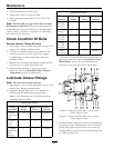
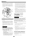
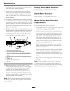
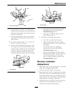
5. Raise the deck to the 5 inch (12.7 cm) height
position (also transport position) and take all force
off of the two large deck lift springs by loosening
the nuts at the front of each spring (
Figure 17).
6. Lower the deck to the 1 inch (2.54 cm) height
position. Force the left rear deck support arm
downward about 1/4 inch (6.4 mm) to get the
deck to rest at the 1 inch height position. Place
locking pliers between the rear swivel and spring
stop to hold the deck in this position (
Figure 17).
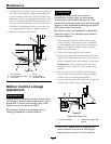
7. Place a 3/4 inch (19 mm) thick block of wood
under each of the two rear anti- scalp roller
brackets and place one under one of the front
center anti-scalp roller brackets.
8. Loosen the two top chain bolts in slots in the rear
deck lift arms. Loosen jam nuts and back off the
socket head adjusting screws on the bottom of
the arms until the chains are just loose. Turn the
socket head adjusting screws in until slack is taken
out of each chain. Tighten the jam nuts. Tighten
39