


Maintenance
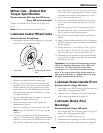
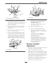
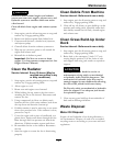
Figure 23
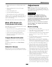
1. Brake mounting bolt
2. Shim
B. Using needle nose pliers, or by hand, take
hold of the tab and remove the shim (Do Not
discard the shim until proper clutch function
has been conrmed).
C. Using a pneumatic line, blow out any debris
from under the brake pole and around the
brake spacers.
D. Re-torque each bolt (M6 x 1) to 10 ft-lb (13
N-m) +/-0.5 ft-lb (0.7 N-m).
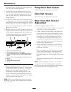
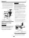
E. Using a 0.010 inch thick feeler gauge, verify
that a gap is present between the rotor and
armature face on both sides of the brake pole
as shown. (Due to the way the rotor and
armature faces wear (peaks and valleys) it is
sometimes difcult to measure the true gap.)
G011733
1
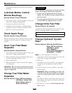
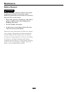
Figure 24
1. Feeler gauge
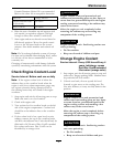
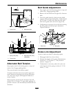
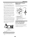
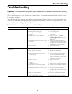
Figure 25
1. Feeler gauge
• If the gap is less than 0.010 inch, then
reinstall the shim and reference the
Troubleshooting section.
• If the gap is sufcient, proceed to the
safety check in step
F.
F. Perform the following safety check:
a. Sit on the seat and start the engine.
b. Make sure the blades Do Not engage
with the PTO switch “off ” and the clutch
disengaged.
If the clutch does not disengage,
reinstall the shim and reference the
Troubleshooting section.
c. Engage and disengage the PTO switch
ten consecutive times to ensure the clutch
is functioning properly. If the clutch
does not engage properly, reference the
Troubleshooting section.
Reverse Indicator
Adjustment
1. Stop engine, wait for all moving parts to stop, and
remove key. Engage parking brake.
2. Unhook seat latch and tilt seat forward.
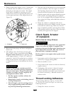
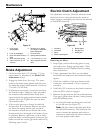
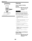
3. Begin with either the left or right motion control
lever. Move lever to the neutral position and pull
lever back until the clevis pin (on arm below pivot
shaft) contacts the end of the slot (just beginning
to put pressure on spring). (Figure 26).
4. Check where lever is relative to notch in console
(should be centered allowing lever to pivot
outward to the neutral lock position).
43