


Maintenance
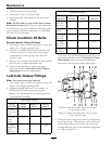
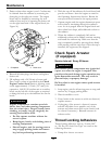
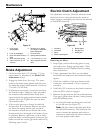
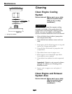
Figure 21
1. Lever down
(disengaged)
6. Remove pin to adjust
rod length for additional
brake adjustment
2. Lever up (engaged)
7. Trunnion roller
3. Nyloc nut below trunnion
roller
8. Spring retainer bracket
4. Nyloc nut below spring
9. 2 13/16 inches (7.1 cm)
5. 1/8 to 3/16 inch (3.2 to
4.8 mm)
10. Jam nut above trunnion
roller
Brake Adjustment
1. Check for brake link 2 13/16 inches (7.1 cm)
measurement as described in the Brake Link
Adjustment section.
2. Engage the brake lever (lever up). The space
between the brake spring bracket and the nyloc
nut under the spring should measure 1/8 inch to
3/16 inch (3.2–4.8 mm).
3. If adjustment is necessary, loosen jam nut above
the trunnion roller. Adjust the nyloc nut under
the trunnion roller until distance listed above
exists between the spring retainer bracket and the
adjacent nyloc nut. Tighten the jam nut above
the trunnion roller.
4. If the correct gap can no longer be achieved
because there is no clearance between the nyloc
nut below the spring and the jam nut above
the trunnion or there are no threads left on the
bottom nyloc nut, the length of the brake rod can
be adjusted. Remove a pin from a yoke at either
end of the brake rod and lengthen (or shorten) the
brake rod until the correct gap can be achieved by
following steps
2 and 3.
Electric Clutch Adjustment
No adjustment necessary. However when the clutch
brake has worn to the point where the clutch no
longer engages consistently, the shim can be removed
to extend the clutch life.
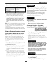
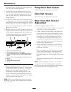
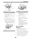
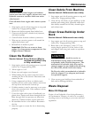
Figure 22
1. Armature 5. Brake spacer
2. Field shell 6. Re-gap shim
3. Rotor 7. Brake pole
4. Brake mounting bolt
Removing the Shim:
1. Stop engine, wait for all moving parts to stop,
and remove key. Engage parking brake. Allow
the machine to cool completely before starting
these instructions.
2. Using a pneumatic line, blow out any debris
from under the brake pole and around the brake
spacers.
3. Check the condition of the wire harness leads,
connectors, and terminals. Clean or repair as
necessary.
4. Verify that 12V is present at the clutch connector
when the PTO switch is engaged.
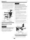
5. Measure the gap between the rotor and armature.
If the gap is greater than .04 inch (1 mm), proceed
with the following steps:
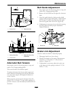
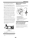
A. Loosen both brake mounting bolts one-half
to one full turn (see
Figure 23).
Note: Do Not remove the brake pole from
the eld shell/armature. The brake pole has
worn to match the armature and needs to
continue to match after the shim is removed
to ensure proper brake torque.
42