


12
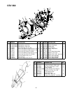
SHARPENING OR REPLACING CHIPPER
BLADES
1. Disconnect the spark plug wire and move away
from the spark plug.
2. Remove the flail screen as instructed in the
previous section.
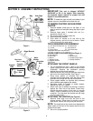
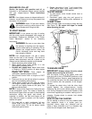
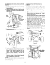
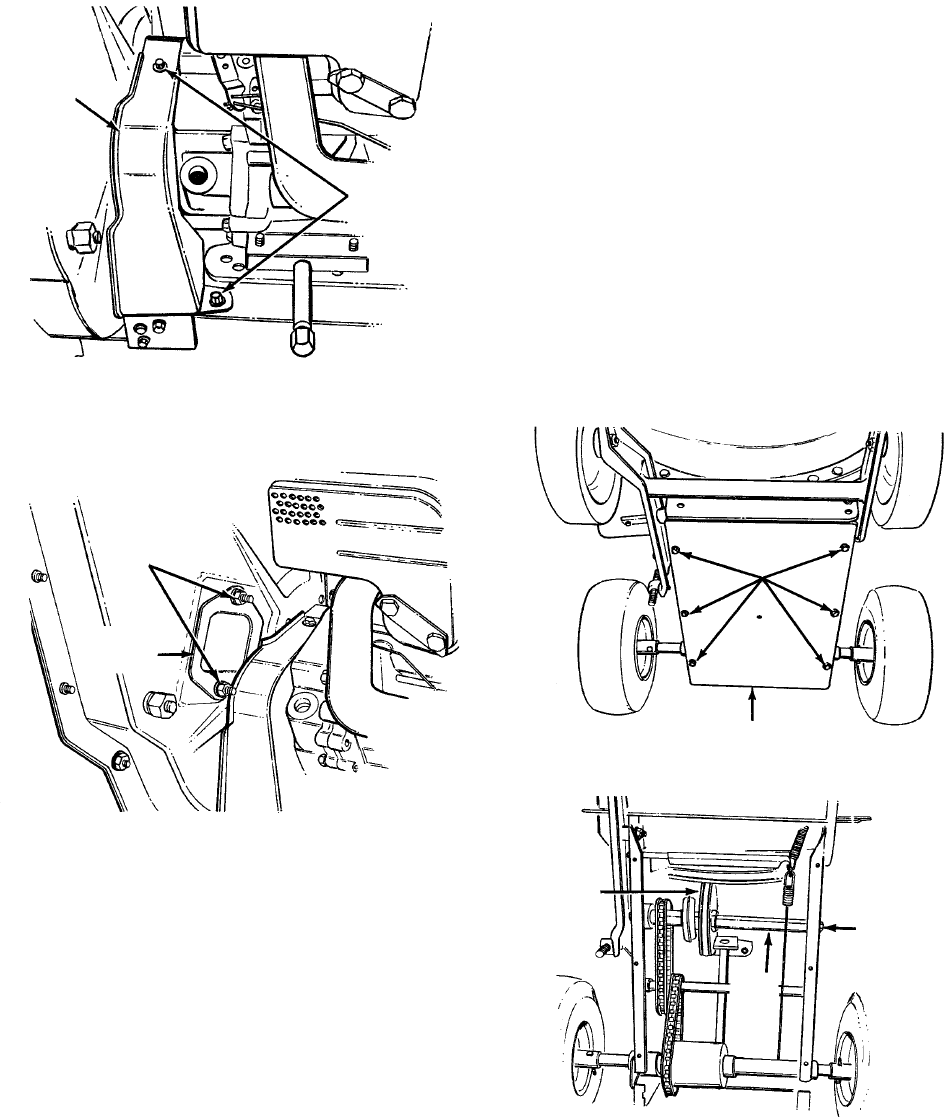
3. Remove the plastic belt cover on the front of the
engine by removing the two self-tapping screws.
See Figure 16.
Figure 16
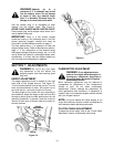
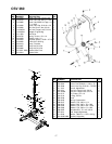
4. Remove the access plate by removing two hex
lock nuts. See Figure 17.
Figure 17
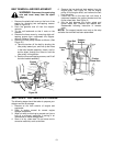
5. Locate one of the chipper blades in the access
plate opening by rotating the impeller assembly
by hand. Remove the blade using a 3/16" allen
wrench on the outside of the blade and 1/2"
wrench on the impeller assembly, inside the
housing. Torque hardware to 250-300 inch
pounds.
6. Remove the other blade in the same manner.
Replace or sharpen blades. If sharpening, make
certain to remove an equal amount from each
blade. Reassemble in reverse order.
NOTE: Make certain blades are reassembled with
the sharp edge facing upward, as viewed from the
access plate opening.
CHANGING THE FRICTION WHEEL
RUBBER
The rubber on the friction wheel is subject to wear
and should be checked after 50 hours of operation,
and periodically thereafter. Replace friction wheel
rubber if any signs of wear or cracking are found.
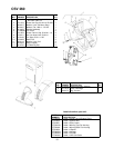
1. Drain the gasoline and oil from the chipper-
vacuum.
2. Tip the unit backward so it rests on the handles.
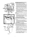
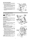
3. Remove the frame cover by removing eight self-
tapping screws from underneath the chipper-
vacuum. See Figure 18.
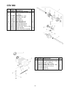
4. Remove the hex shaft from the unit by removing
the hex bolts, lock washers and flat washers
from each side of the frame. See Figure 19. Hold
the friction wheel assembly, and slide the hex
shaft out of the unit toward the right side.
5. Remove the six screws from the friction wheel
assembly (three from each side). Remove the
friction wheel rubber from between the friction
wheel plate.
6. Reassemble new friction wheel rubber to the
friction wheel assembly, tightening the six
screws in rotation and with equal force.
7. Slide the friction wheel assembly up onto the
shift mechanism, then slide the hex shaft back
into the unit. Reassemble in reverse order.
8. Readjust the clutch cable. Refer to adjustment
section.
Figure 18
Figure 19
Self-Tapping
Screws
Belt
Cover
Hex
Lock Nuts
Access
Plate
Self-Tapping
Screws
Frame Cover
Friction
Wheel
Hex Bolt
Lock Washer
Flat Washer
Hex
Shaft