


11
• To mark the hole to ensure proper centering of the
new hole to be drilled, place the pointed end of a
center punch on the cross hairs of new hole
position. Using a hammer, strike the end of the
center punch to create a permanent mark in the
metal frame and carefully remove the template.
• Using a 7/16” drill bit, set it on the mark just made
by the center punch and drill completely through
the frame. Carefully remove any sharp edges
around the hole with a file.
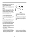
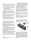
Figure 8
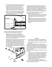
Move to the right side of the tractor and locate the
existing hole to be enlarged. Refer to Figure 8.
• Again using the 7/16” drill bit, carefully drill
completely through the hole marked “Enlarged
Hole” as shown in Figure 8. The original hole in the
tractor’s frame is not large enough to accommodate
the correct mounting hardware.
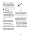
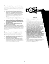
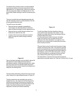
• With both holes drilled to the correct dimension, the
shoulder bolts and related hardware need to be
installed. Both shoulder bolts are identical but the
one that will be mounted on the left side receives
the extra washer which is thinner than the other
two. Refer to Figure 9 for the correct mounting of
the hardware. Reinstall the rear wheels and remove
the frame blocks.
Figure 9
Hydraulic Pump Assembly Hanging Brackets
The hydraulic pump assembly attaches to the tractor
using hangers that are permanently affixed to the
tractor’s frame. These brackets are shipped with the
hydraulic pump assembly. The hardware to mount the
brackets to the tractor is shipped attached to the
brackets and will need to be removed before installing.
The side frame brackets will require two 9/16”
wrenches to install on the tractor.
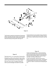
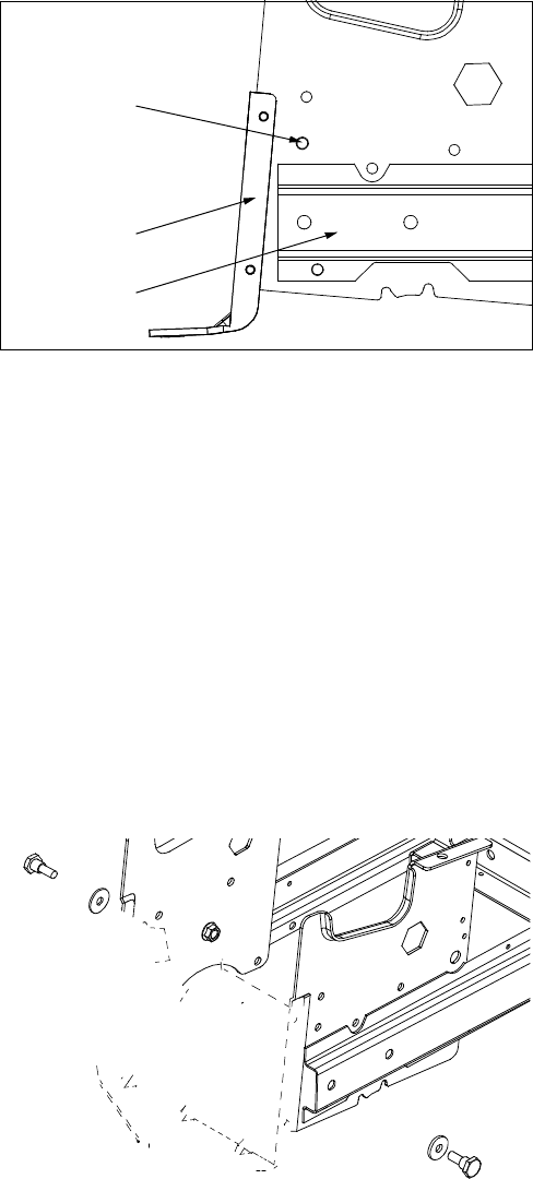
• Install the bolts from the outside of the frame with
the threads on the inside of the frame. Use Figure
10 to determine the position of the hole in the
frame.
• Holding the bolt through the hole with one hand,
slide the small hole of the side frame bracket over
the bolt threads making certain that the curved
portion of the bracket is facing outward. Refer to
Figure 10.
Figure 10
• Thread the locking nut onto the bolt threads and
tighten. Repeat this step on the other side. These
brackets will not need to be removed when using a
mower deck.
The rear mounting bracket for the hydraulic pump
assembly has two bolts and lock nuts that hold it to the
tractor’s frame. This bracket will be mounted toward the
rear of the tractor directly in between the left and right
frame rails. Refer to Figure 10 for the correct location of
the mounting holes.
Installing the rear mounting bracket will require two 3/4”
wrenches.
• First position the rear mounting bracket against the
cross bar on the rear of the frame with the long
slotted lower portion toward the rear of the tractor.
• The cross bar has holes drilled to match those on
the rear mounting bracket. Align the holes and
install the bolts with the threaded part of the bolt
toward the back of the tractor.
• Thread on the locking nuts and tighten firmly.
The rear mounting bracket will not need to be removed
when a mowing deck is installed.
Frame Rail
Hitch Plate
Enlarged Hole
(Drill Here)