


10
IMPORTANT: If working on or with the battery for any
reason, disconnect the NEGATIVE (Black) wire from it’s
terminal first, followed by the POSITIVE (Red) wire.
When reattaching the battery cables, always connect
the POSITIVE (Red) wire to the positive (+) battery
terminal first, followed by the NEGATIVE (Black) wire to
the negative (-) battery terminal. Be certain that the
wires are connected to the correct terminals, reversing
them could change the polarity of the battery and cause
damage to your engine’s alternating system.
WARNING: Batteries contain an explosive
gas. Work on the battery in a well ventilated
area and do not allow a spark or an open
flame near the battery.
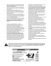
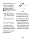
Working under the hood again, there are two wires that
need to be connected. These wires provide power to
the wiring harness for the electric lift cylinder.
• The terminal connector attached to the short blue
wire needs to be connected to the positive side of
the battery. This is the wire with the fuse holder
attached. Connect this wire along with the red
(positive) battery cable to the positive side of the
battery.
• The short black wire in the lift switch wiring harness
needs to be connected along with the black
(negative) battery cable to the negative side of the
battery.
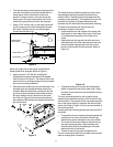
Attachment Hitch Mounting Bolts
The attachment hitch, which will mount over the
hitchplate on the rear of the tractor, requires the
permanent installation of mounting bolts that the
attachment plate will hang on once installed.
Locate the shoulder bolts, washers, and locking nuts
that are packed separately in the box with the
attachment hitch.
To mount the shoulder bolts, a drill with a 7/16” drill bit
will be used. Drilling the holes in the frame will require
the rear tires of the tractor to be removed. Be certain to
stabilize the tractor with blocks or jack stands to prevent
it from tipping while the rear wheels are off.
IMPORTANT: Some newer units may already have the
necessary mounting holes drilled to the correct size.
Read the following instructions up to the bulleted
paragraph on page 11 above Figure 9 to verify if the
tractor’s frame needs to be drilled.
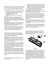
Figure 6
Removing the Rear Wheels
To remove the rear wheels, a 3/4” socket with an
extension, or a star (lug nut) wrench with a 3/4”
opening, is necessary. Loosen the four lug nuts slightly
that hold each wheel on before jacking the rearend of
the tractor up. Raise the rearend of the tractor up, block
the frame of the tractor for support, and remove the
lugnuts and wheels on both sides of the machine.
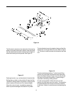
Installing the Shoulder Bolts
There is a template located on page 25 that will be used
to locate the exact position for drilling the hole. Follow
the instructions given on that page for cutting the
template correctly. Figure 6 shows the basic location
where the following work will be performed with the
tractor’s body parts eliminated for clarity.
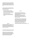
• Working on the left side of the frame in the rear of
the tractor as shown in Figure 7, attach, with tape,
the template which was cut out from the back of this
manual. Make certain that the lower edge of the
template piece is lined up along the top edge of the
frame rail. Also, align the right side of the template
piece along the left edge of the hitch plate, and be
certain the left half of the existing hole on the tractor
frame is exposed and lined up with the half of the
marked existing hole on the template. It is critical
that the template is set correctly for proper drilling.
Refer to Figure 7.
Figure 7