


ASSEMBLY
Read these instructions in their entirety before you attempt to assemble your new chipper/vaco Your new chipper/vac
has been completely assembled at the factory, except for the items shown in Figure 1.. To ensure proper operation of
your chipper/vac, all nuts and bolts must be securely tightened when changing the configuration of the machine Use
the correct tools as necessary to ensure proper tightness.
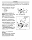
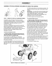
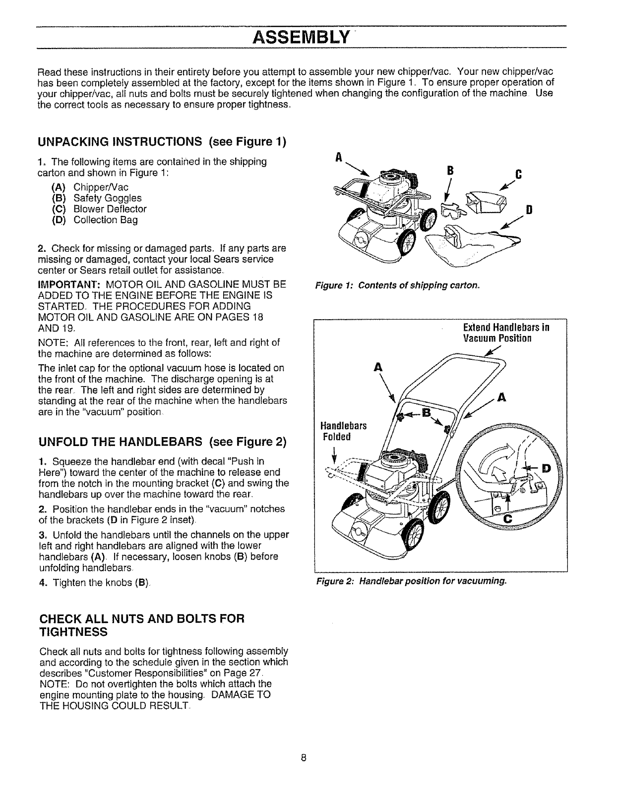
UNPACKING INSTRUCTIONS (see Figure 1)
1, The following items are contained in the shipping A
carton and shown in Figure 1: _ B C
(A) Chipper/Vac //
(B) Safety Goggles __P'
(C) Blower Deflector
(D) Collection Bag J
2. Check for missing or damaged parts.. If any parts are
missing or damaged, contact your local Sears service
center or Sears retail outlet for assistance
IMPORTANT: MOTOR oIL AND GASOLINE MUST BE
ADDED TO THE ENGINE BEFORE THE ENGINE IS
STARTED_ THE PROCEDURES FOR ADDING
MOTOR OIL AND GASOLINE ARE ON PAGES 18
AND 19.
NOTE: All references to the front, rear, left and right of
the machine are determined as follows:
The inlet cap for the optional vacuum hose is located on
the front of the machine. The discharge opening is at
the rear The left and right sides are determined by
standing at the rear of the machine when the handlebars
are in the "vacuum" position
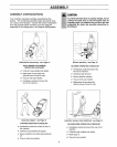
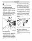
UNFOLD THE HANDLEBARS (see Figure 2)
1, Squeeze the handlebar end (with decal "Push in
Here") toward the center of the machine to release end
from the notch in the mounting bracket (C) and swing the
handlebars up over the machine toward the rear.
2. Position the handlebar ends in the "vacuum" notches
of the brackets (D in Figure 2 inset).
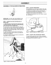
3o Unfold the handlebars until the channels on the upper
left and right handlebars are aligned with the lower
handlebars (A) If necessary, loosen knobs (B) before
unfolding handlebars.
4_ Tighten the knobs (B)
Figure 1: Contents of shipping carton.
ExtendHandlebarsin
VacuumPosition
A
\
Handlebars
Folded
Figure 2: Handlebar position for vacuuming.
CHECK ALL NUTS AND BOLTS FOR
TIGHTNESS
Check all nuts and bolts for tightness following assembly
and according to the schedule given in the section which
describes "Customer Responsibilities" on Page 27.
NOTE: Do not overtighten the bolts which attach the
engine mounting plate to the housing DAMAGE TO
THE HOUSING COULD RESULT