


ASSEMBLY
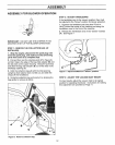
CAUTION
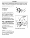
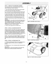
STEP 2: INSTALL COLLECTION BAG
For walk-behind vacuuming or using the chipper, install
the collection bag as described below.
1. Stop the engine, disconnect the spark plug wire
from the spark plug, and make sure that all moving
parts have come to a complete stop.
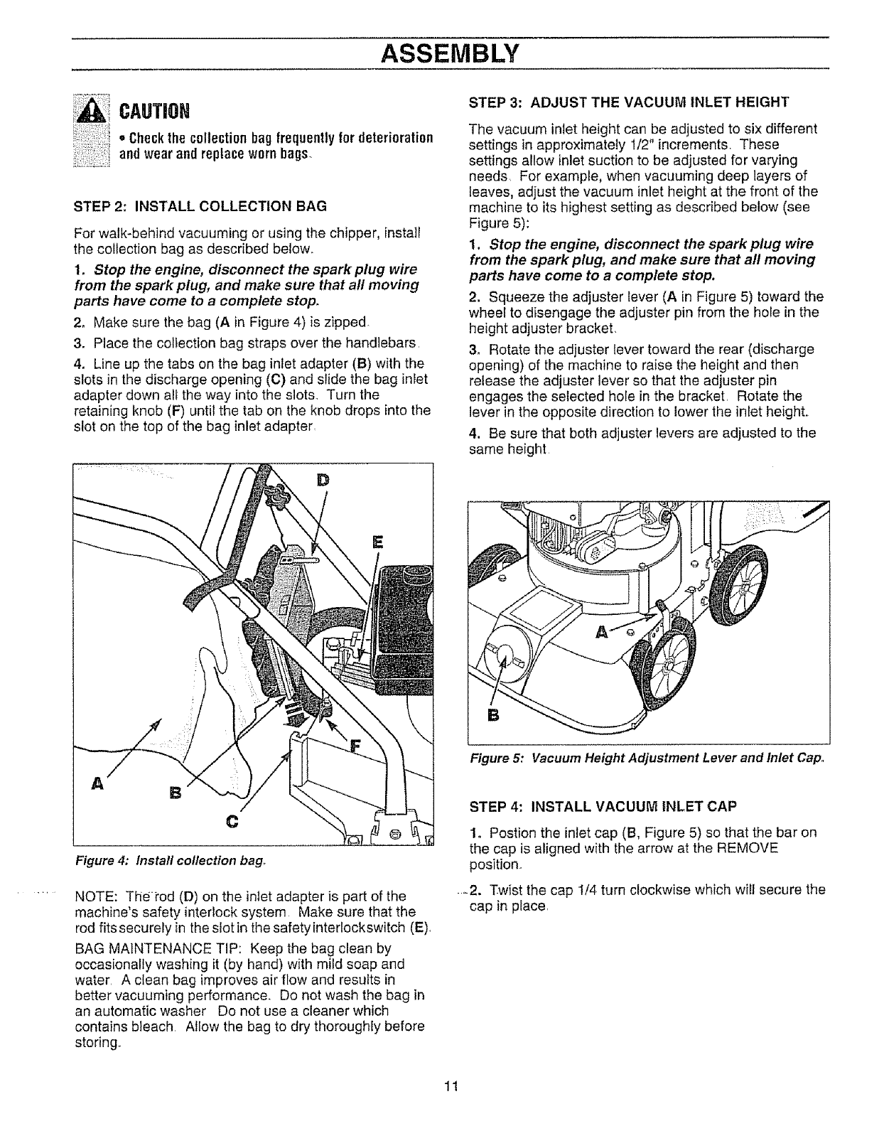
2, Make sure the bag (A in Figure 4) is zipped
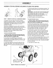
3. Place the collection bag straps over the handlebars,
4. Line up the tabs on the bag inlet adapter (B) with the
slots in the discharge opening (C) and slide the bag inlet
adapter down all the way into the slots. Turn the
retaining knob (F) until the tab on the knob drops into the
slot on the top of the bag inlet adapter
Figure 4: Install collection bag.
NOTE: Thei'od (D) on the inlet adapter is part of the
machine's safety interlock system Make sure that the
rod fits securely in the slot in the safety interlockswitch (E).
BAG MAINTENANCE TIP: Keep the bag clean by
occasionally washing it (by hand) with mild soap and
water A clean bag improves air flow and results in
better vacuuming performance, Do not wash the bag in
an automatic washer Do not use a cleaner which
contains bleach Allow the bag to dry thoroughly before
storing,
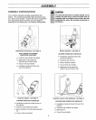
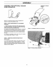
STEP 3: ADJUST THE VACUUM INLET HEIGHT
The vacuum inlet height can be adjusted to six different
settings in approximately 1/2" increments. These
settings allow inlet suction to be adjusted for varying
needs, For example, when vacuuming deep layers of
leaves, adjust the vacuum inlet height at the front of the
machine to its highest setting as described below (see
Figure 5):
1. Stop the engine, disconnect the spark plug wire
from the spark plug, and make sure that all moving
parts have come to a complete stop,
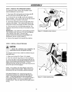
2. Squeeze the adjuster lever (A in Figure 5) toward the
wheel to disengage the adjuster pin from the hole in the
height adjuster bracket,
3. Rotate the adjuster lever toward the rear (discharge
opening) of the machine to raise the height and then
release the adjuster lever so that the adjuster pin
engages the selected hole in the bracket, Rotate the
lever in the opposite direction to lower the inlet height.
4. Be sure that both adjuster levers are adjusted to the
same height
B
Figure 5: Vacuum Height Adjustment Lever and Inlet Cap.
STEP 4: INSTALL VACUUM INLET CAP
1. Postion the inlet cap (B, Figure 5) so that the bar on
the cap is aligned with the arrow at the REMOVE
position.
-2. Twist the cap 1/4 turn clockwise which will secure the
cap in place,
11