


SERVICE AND ADJUSTMENTS
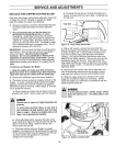
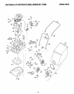
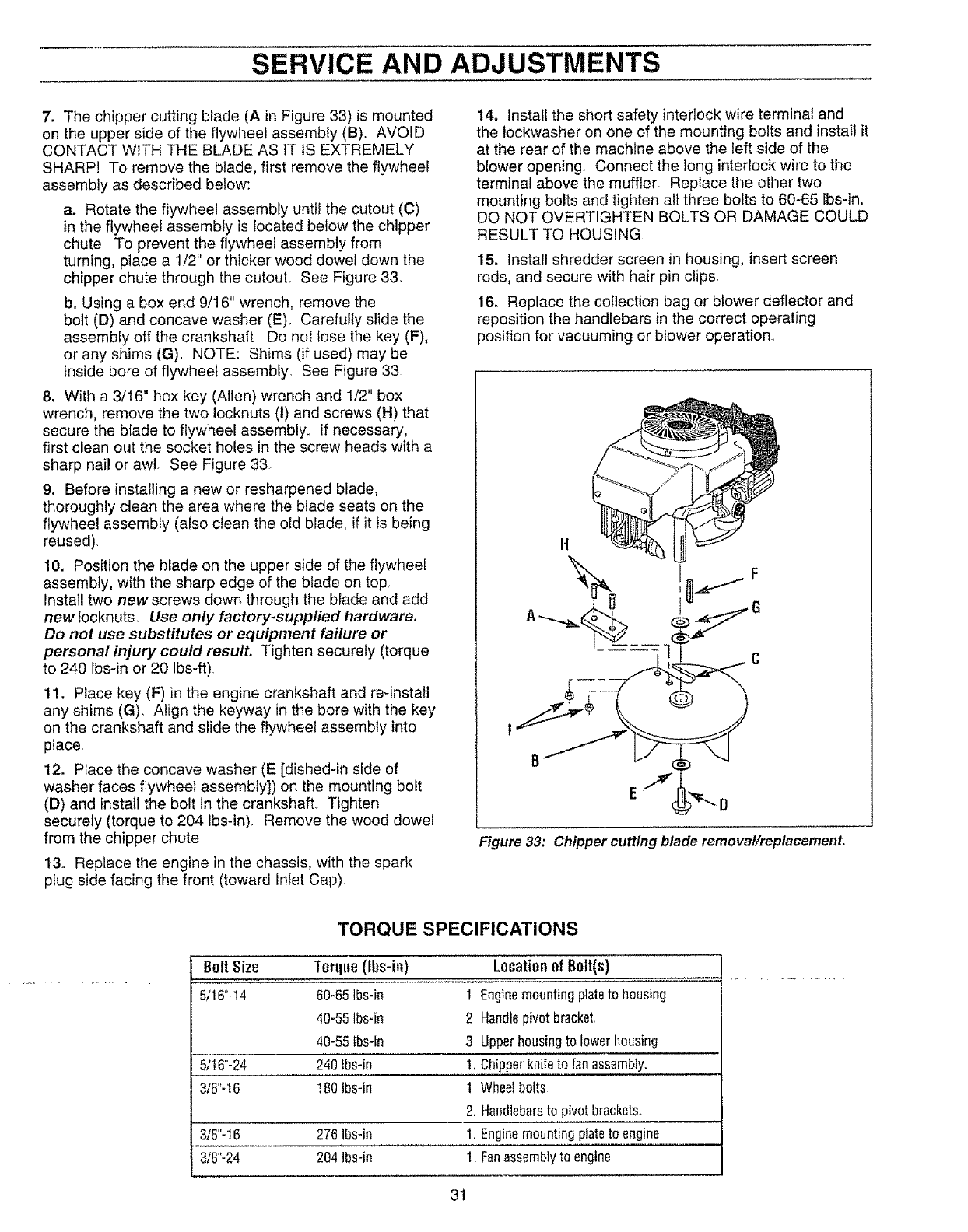
7, The chipper cutting blade (A in Figure 33) is mounted
on the upper side of the flywheel assembly (B). AVOID
CONTACT WITH THE BLADE AS IT tS EXTREMELY
SHARP! To remove the blade, first remove the flywheel
assembly as described below:
a. Rotate the flywheel assembly until the cutout (C)
in the flywheel assembly is located below the chipper
chute, To prevent the flywheel assembly from
turning, place a 1/2" or thicker wood dowel down the
chipper chute through the cutout. See Figure 33.
b, Using a box end 9/16" wrench, remove the
bolt (D) and concave washer (E) Carefully slide the
assembly off the crankshaft Do not lose the key (F),
or any shims (G), NOTE: Shims (if used) may be
inside bore of flywheel assembly, See Figure 33
8. With a 3/16" hex key (Allen) wrench and 1/2" box
wrench, remove the two Iocknuts (I) and screws (H) that
secure the blade to flywheel assembly., If necessary,
first clean out the socket holes in the screw heads with a
sharp nail or awl, See Figure 33
9. Before installing a new or resharpened blade,
thoroughly clean the area where the blade seats on the
flywheel assembly (also clean the old blade, if it is being
reused).
10. Position the blade on the upper side of the flywheel
assembly, with the sharp edge of the blade on top,
Install two new screws down through the blade and add
new focknuts_ Use only factory-supplied hardware.
Do not use substitutes or equipment failure or
personal injury could result. Tighten securely (torque
to 240 lbs-in or 20 Ibs-ft)
11. Place key (F) in the engine crankshaft and re-install
any shims (G). Align the keyway in the bore with the key
on the crankshaft and slide the flywheel assembly into
place
12. Place the concave washer (E [dished-in side of
washer faces flywheel assembly]) on the mounting bolt
(D) and install the bolt in the crankshaft. Tighten
securely (torque to 204 Ibs-in) Remove the wood dowel
from the chipper chute
13. Replace the engine in the chassis, with the spark
plug side facing the front (toward Inlet Cap)
14. Install the short safety interlock wire terminal and
the lockwasher on one of the mounting bolts and install it
at the rear of the machine above the left side of the
blower opening. Connect the long interlock wire to the
terminal above the muffler. Replace the other two
mounting bolts and tighten all three bolts to 60-65 Ibs-in.
DO NOT OVERTIGHTEN BOLTS OR DAMAGE COULD
RESULT TO HOUSING
15. install shredder screen in housing, insert screen
rods, and secure with hair pin clips.
16. Replace the collection bag or blower deflector and
reposition the handlebars in the correct operating
position for vacuuming or blower operation°
Figure 33t Chipper cutting blade removal/replacement,
TORQUE SPECIFICATIONS
BoltSize Torque(Ibs-in) Locationof Bolt(s)
5/16"-t4 60-65]Bs-in 1 Enginemountingplatetohousing
40-55Ibs-in 2 Handlepivotbracket
40-55tbs-in 3 Upperhousingto lowerhousing
5/16"-24 240tbs-in 1. Chipperknifeto fanassembly.
3/8"-t6 180lbs-in 1 Wheelballs
2. Handlebarstopivotbrackets.
3/8"-16 276lbs-in 1. Enginemountingplateto engine
3/8"-24 204lbs-in 1 Fanassemblyto engine
31