


4-7
Routine Service and Maintenance
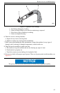
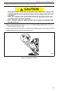
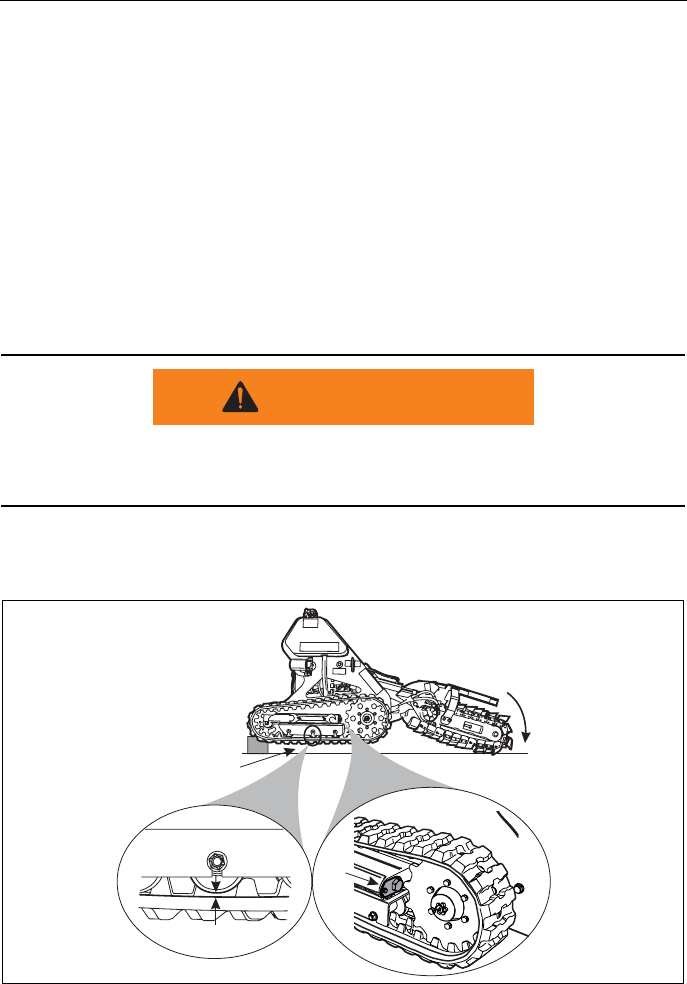
b. Place a solid object, such as a concrete block or 8" H x 8" W x 48" L piece of lumber,
under the operator's platform.
c. Tilt the trencher boom downwards until the lowest cutting edge is touching the ground.
See Figure 4-6.
d. Continue to lower the boom assembly, pushing the front of the machine upwards.
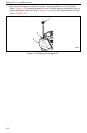
Continue raising the machine until the front drive sprocket and rear idler rollers are off the
ground. Shut off the engine.
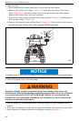
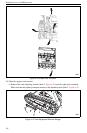
e. Measure the gap between the bottom of the center bogey guide roller (Item 1, Figure 4-6)
and the track. The proper tension will be about a 1/4" - 3/8" deflection.
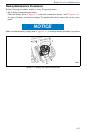
f. If an adjustment is needed, remove the adjustment nut lock plate and rotate the tension
adjustment nut (Item 2, Figure 4-6) until the proper track deflection measurement is
achieved. Reinstall and secure the adjustment nut lock plate.
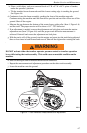
g. With the tracks still off the ground, start the engine and rotate just the track being adjusted
three or four times in both forward and reverse. Shut off the engine after rotating the track.
DO NOT activate either the trencher operator presence control or trencher operation
lever while testing the track assembly. This could cause an unstable condition on the
machine.
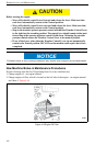
h. Shut off the engine and re-measure the deflection dimension.
i. Repeat the measurement and adjustment procedure on the other track assembly.
j. Lower the machine onto the ground.
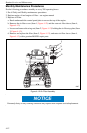
Figure 4–7 Track Deflection Measurement and Adjustment
WARNING
1/4” - 3/8”
1
2
2454