


6-7-06 - Fifth Proof
3-19
Pre-Start Inspection and Operation
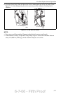
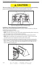
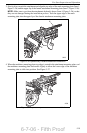
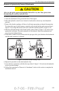
3. Slowly drive towards the attachment and align the top edge of the male mounting plate (Item 1,
Figure 3–26) and the upper lip of the female attachment mounting plate (Item 2, Figure 3–26).
NOTE: Make sure to position the attachments hydraulic hoses (Item 4, Figure 3–26) so that
they are not damaged during the installation process. Tuck the upper edge of the male
mounting plate into the upper lip of the female attachment mounting plate.
Figure 3–26 Hydraulically Powered Attachment Installation
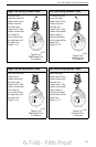
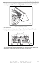
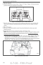
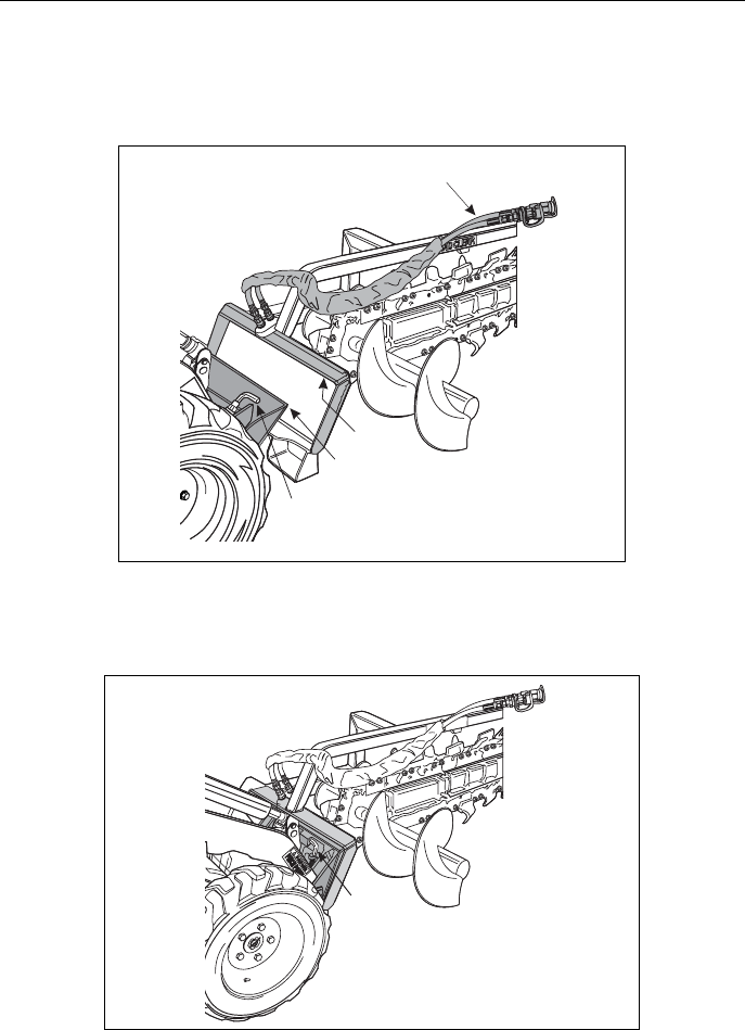
4. When the machines mounting plates top edge is seated in the attachment mounting plate, curl
the machines mounting plate backwards slightly to allow the lower edge of the machines
mounting plate to slide into position. See Figure 3–27.
Figure 3–27 Hydraulically Powered Attachment Installed
2
1
4
3
2023
1
2032