


Cisco Confidential - Draft 1
2-17
Cisco Aironet 1500 Series Outdoor Mesh Access Point Hardware Installation Guide
OL-9977-05
Chapter 2 Mounting Instructions
Mounting the Access Point
Caution When the product is installed outside of the building, and the DC power/Ethernet connection
is used, this cabling should be installed in accordance with the requirements of a Class 2
circuit, as detailed in Article 725 of the National Electric Code (NEC). Such requirements
include, but are not limited to, routing the Class 2 cabling away from AC power lines and AC
building wiring, and limiting the exposed cable runs external to the building to less than 140
ft (42 m) – or is directly buried or in underground conduit, where a continuous metallic cable
shield or a continuous metallic conduit containing the cable is bonded to each building
grounding electrode system. If such installation methods are not used, the cabling must be
installed according to the requirements for telecommunication circuits (TNV) as detailed in
Article 800, which includes requirements for a Listed primary protector upon entering the
building, and limits the installation to only Listed networking equipment designed to
accommodate telecommunication interfaces.
Use only the specified power injector (AIR-PWRINJ1500=) for the access point. This power injector is
designed to meet the power requirements of the access point and is a listed Class 2 Limited Power Source
(LPS).
Tip To forward bridge traffic, add a switch between the power injector and controller. Refer to the
Deployment Guide: Cisco Mesh Networking Solution for more information.
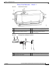
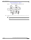
Step 3 Ensure the antennas are connected to the access point before you apply power to the access point.
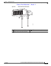
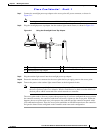
Step 4 Connect a shielded outdoor-rated Ethernet cable (such as AIR-ETH1500-150=) between the power
injector and the access point’s Ethernet connector (see Figure 2-2).
Note You should hand-tighten the access point Ethernet cable connector until the connector locks.
Warning
Use the captive connector cap on the unused mil spec connector to prevent water intrusion and
possible safety hazards.
Statement 362
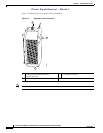
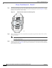
Step 5 When using the optional Cisco external omnidirectional antennas, connect them to the access point as
shown in Figure 2-1. When using other Cisco external antennas, mount them as directed by the
installation documentation that shipped with the antennas.
Step 6 When using optional third-party external antennas, mount and connect them as described in the
installation documents that shipped with the antennas.
Step 7 Continue with the “Grounding the Access Point” section on page 2-21.
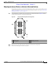
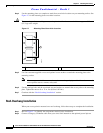
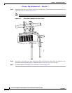
Mounting the Access Point on a Pole
When installing an access point on a pole or mast, you should use the optional Cisco pole mount kit. To
mount the access point on a pole, perform these steps: