


INTRODUCTION
This section describes the location and
function of the controls on your tiller.
Refer to Section 4: Operation for detailed
operating instructions.
Practice using these controls, with the
engine shut off, until you understand the
operation of the controls and feel confi-
dent with each of them.
IMPORTANT: Refer to the separate engine
manufacturer’s Engine Owner’s Manual for
information about the controls on the
engine.
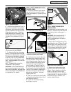
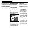
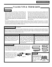
WHEEL GEAR LEVER
This lever (A, Figure 3-1) has two posi-
tions: ENGAGE and DISENGAGE.
In the ENGAGE position, the wheels will
start turning when the Forward Clutch
Control (the tines will also start turning
when the clutch is engaged).
The DISENGAGE (freewheel) position
places the wheels in the freewheeling
mode to allow the unit to be moved
without the engine running. Use the DIS-
ENGAGE position only when the engine is
not running. See “DANGER” statement
that follows.
To shift to ENGAGE, gently (do not force)
move the lever forward while also rolling
the tiller a few inches forward or back-
ward. Moving the tiller helps to align the
shift mechanism with the transmission
wheel drive gears.
To shift to DISENGAGE, move the lever
rearward, without rolling the tiller. The
wheels will roll freely when the lever is
properly set into the DISENGAGE position.
FORWARD CLUTCH CONTROL
LEVERS
The two interconnected levers (B, Figure
3-1) control the engagement of forward
drive to the wheels and tines.
To Operate the Forward Clutch Control:
1. Before engaging the Forward Clutch
Control Levers, put the Wheel Gear Lever
in the ENGAGE position (see “WARNING”
above).
2. Lift and hold one or both of the levers
against the handlebar grips to engage the
wheels and tines.
3. Release BOTH levers to disengage
(stop) the wheels and tines. All forward
motion will stop (the engine will continue
to run).
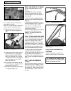
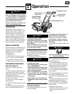
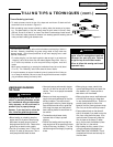
DEPTH REGULATOR LEVER
This lever (D, Figure 3-2) controls the
tilling depth of the tines. Pull the lever
straight back and slide it up or down to
engage the notched height settings.
The highest notch (lever all the way down)
raises the tines approximately 1-1/2
inches off the ground. This “travel” posi-
tion allows the tiller to be moved without
the tines digging into the ground.
Features and Controls
3
Section
9
Figure 3-1: Controls located on handlebar.
Never place the Wheel Gear Lever in
DISENGAGE (Freewheel) when the
engine is running.
Having the Wheel Gear Lever in
DISENGAGE and then engaging the
tines/wheels with the Forward Clutch
Control Lever could allow the tines to
propel the tiller rapidly forward.
Failure to follow this instruction could
result in personal injury or property
damage.
DANGER
Never engage the wheels and tines with
Forward Clutch Control unless the
Wheel Gear Lever is in ENGAGE.
Engaging Forward Clutch Control Levers
when the wheels are not engaged could
allow the tines to rapidly propel the
tiller forward.
Failure to follow this warning could
result in personal injury or property
damage.
WARNING
Before operating your machine, care-
fully read and understand all safety,
controls and operating instructions in
this Manual, in the separate Engine
Owner’s Manual, and on the decals on
the machine.
Failure to follow these instructions can
result in serious personal injury.
WARNING
A
• Use extreme caution when reversing or
pulling the machine towards you. Look
behind to avoid obstacles.
• Never attempt to till when reversing.
Failure to follow this warning could
result in personal injury or property
damage.
WARNING
B
Figure 3-2: Depth Regulator Lever.
D
• Do not attempt to till too deeply too
quickly. Gradually work down to
deeper tilling depths.
• Place the Depth Regulator Lever in the
“travel” position before starting the
engine. This position prevents the
tines from touching the ground until
you are ready to begin tilling.
Failure to follow this warning could
result in personal injury or property
damage.
WARNING