


INTRODUCTION
Carefully follow these assembly steps to
correctly prepare your tiller for use. It is
recommended that you read this Section
in its entirety before beginning assembly.
INSPECT UNIT
Inspect the unit and carton for damage
immediately after delivery. Contact the
carrier (trucking company) if you find or
suspect damage. Inform them of the
damage and request instructions for filing
a claim. To protect your rights, put your
claim in writing and mail a copy to the
carrier within 15 days after the unit has
been delivered. Contact us at the factory if
you need assistance in this matter.
UNPACKING AND ASSEMBLY
INSTRUCTIONS
STEP 1: UNPACKING INSTRUCTIONS
1. Remove any cardboard inserts and
packaging material from the carton.
Remove any staples from the bottom of
the carton and remove the carton.
2. Cut the large, plastic tie strap that
secures the transmission tube to the ship-
ping pallet. Leave the handlebars on top of
the tiller to avoid damaging any cables.
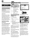
3. A bag with loose hardware is inside the
literature envelope. Check the contents
against the following list and Figure 2-1.
Contact your local dealer or the factory if
any items are missing or damaged.
4. The tiller is heavy. You should not
attempt to remove it from the shipping
platform until instructed to do so in these
“Assembly” steps.
HARDWARE BAG PARTS LIST
Fig.
Ref. Qty. Description
1 2 3/8-16 x 1" Hex Hd. Screw
2 1 Keyed Washer
3 1 Wheel Gear Lever Knob
4 1 Height Adjustment Flange
Screw (See Figure 2-1A)
5 2 3/8" Flat Washer
6 2 #10 Lockwasher
7 2 3/8"-16 Nylock Lock Nut
8 2 #10-32 x 1/2" Round Hd.
Screw
9 1 Cotter Pin (not used)
10 4 Plastic Tie Strap (2 not used)
Tools/Materials Needed
for Assembly
(1) 3/8" open-end wrench*
(2) 9/16" open-end wrench*
(1) Scissors (to trim plastic ties)
(1) Ruler
(1) Small board (to tap plastic knob on
lever)
(1) Tire pressure gauge
(1) Clean oil funnel
(1) Clean, high-quality motor oil. Refer to
the separate Engine Owner’s Manual
for motor oil specifications and
quantity required.
* Adjustable wrenches may be used.
IMPORTANT: Motor oil must be added to
the engine crankcase before the engine is
started. Follow the instructions in this
“Assembly” Section and in the separate
Engine Owner’s Manual.
NOTE: LEFT and RIGHT sides of the tiller
are as viewed from the operator’s position
behind the handlebars.
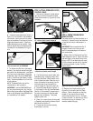
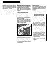
STEP 2: ATTACH HANDLEBARS
1. Cut the large, plastic cable ties that
secure the handlebar ends to the handle-
bar mounting tabs on the transmission
top cover.
2. Gently lift handlebar (do not over-
stretch attached cable) and place handle-
bar cross-brace (B, Figure 2-2) in front of
curved height adjustment bracket (C).
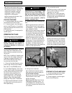
3. With forward clutch cable (N, Figure
2-3) on inside of handlebar, position
handlebar ends on outside of the two
mounting tabs (M, Figure 2-2) on trans-
mission top cover.
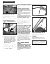
4. Loosely attach the handlebars to the
mounting tabs with two 3/8-16 x 1"
screws (heads of screws go to inside of
tabs), 3/8" flat washers and 3/8"-16 lock
nuts (O, Figure 2-3).
5. Move the handlebars up or down to
align the threaded hole in the cross-brace
with one of the four slots in the curved
height adjustment bracket. Place the
keyed washer (E, Figure 2-2) on the flange
head height adjustment screw (F) with the
raised keys (edges) of the washer facing
down.
Assembly
2
Section
6
Figure 2-2: Forward clutch control cable not
shown for clarity.
Figure 2-1: Loose hardware (shown in
reduced size).
Figure 2-1A Handlebar height adjustment
uses the flange head screw.
31
2
4
5
6
10
7
8
E
F
C
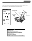
To prevent personal injury or property
damage, do not start the engine until all
assembly steps are complete and you
have read and understand the safety and
operating instructions in this Manual.
WARNING
Flange
9
B
M